

What the module calculates
Westergaard areas gives the increase in vertical stress at a point below one or several uniformly loaded, flexible circles and rectangles on the ground surface, when the ground is Westergaard’s material (Westergaard 1938): an elastic soil that is stiffened by thin, rigid horizontal layers, which stop it spreading sideways. You choose the point A by its position x, y on the ground and its depth z, and the module gives Δσz there, with Boussinesq’s value for the same loads beside it for comparison. It draws the lines of equal stress, the colour contours, the profile with depth under A and a 3D view.
Westergaard’s point load Q gives, at a horizontal distance r from it and the depth z,
where μs is Poisson’s ratio of the soil between the rigid layers. The module integrates this over each loaded area. Two results are closed forms: below the centre of a circle of radius R, and below a corner of a rectangle:
For any other point the module integrates Westergaard’s point load over the circle, or adds and subtracts four rectangles that each have a corner above A. With several areas the stress of each is found with its own geometry and the stresses are added. The result is also given as the influence value Δσz/q when there is one area.
What you can describe
- One to eight loaded areas, each a circle (radius R) or a rectangle (L along x, B along y), each with its own load per unit area q and the position (xc, yc) of its centre on the ground.
- The point A: x and y on the ground surface, in the same coordinates as the centres, and the depth z.
- Poisson’s ratio μs of the soil between the rigid layers, from 0 to 0.49.
- The depth of the profile zmax, down to which the Profile view and the table under A run.
The result is the increase caused by the loads only; the overburden pressure of the soil above A is not included, so add it where your design needs the total stress.
Which module for which load
- A homogeneous elastic ground (no rigid layers): Circle, any point, Rectangle, Vertical strip load, Embankment or, for any shape in plan, Influence chart.
- A concentrated load on Westergaard’s material: Westergaard point load.
- This module gives circles and rectangles only. For a strip, an embankment or a load of another shape, use the modules above and add the stresses.
Before you start: what you need
Have these ready from your design:
| What | Notes |
|---|---|
| What Where it comes from | Notes |
| The loaded areas Your layout | For each: circle or rectangle; the load per unit area q (zero or more, a pressure, not a force); the radius R or the sides L and B (at least 0.001 m); the position of the centre. Areas may touch but not overlap. |
| The point A Where you want the stress | x and y on the ground in the coordinates of the centres; the depth z at least 0.001 m. |
| Poisson’s ratio μs Your assumption for the soil between the rigid layers | From 0 to 0.49. The module opens with 0. |
| The depth of the profile zmax How deep you want to read | At least 0.1 m. |
Quick start in eight steps
- Open the module and choose the units
Open Westergaard areas from the Stresses in a Soil Mass family. Pick SI · kN, SI · tf or US in the header; you can change it at any time.
- Enter the loaded areas
In Loaded areas the first area, a circle, is already in the table. Press its row to change it, or drag it on the drawing. To add another, choose Circle or Rectangle in the New loaded area form, fill it in and press + Add loaded area.
- Place the point A
In Point A type x, y and z, or drag the blue point on the Section drawing.
- Set the soil
In Westergaard material type Poisson’s ratio μs.
- Set the depth of the profile
In Depth profile type zmax, or drag the dashed line near the bottom of the drawing.
- Press Analyze
Press Analyze at the foot of the Model tab. The bar reads Analysed and the areas lock; the point A and the profile depth stay free.
- Read the answer
The Results tab gives Δσz at A in Westergaard’s material, Boussinesq’s value for comparison, the influence value for one area and the part from each area for several, then a table against depth. The lines of equal stress are on the Section drawing, the colour bands in Contours.
- Move A and take the report
Drag A or change x, y and z: the stress there is calculated at once. The Calculations tab writes out the working; the Report tab saves a PDF or a Word file.
The screen: section, contours, profile and 3D
The layout is the one every GeoTerva module shares, described in the workspace guide. For this module the drawing has four views, chosen with the buttons above it:
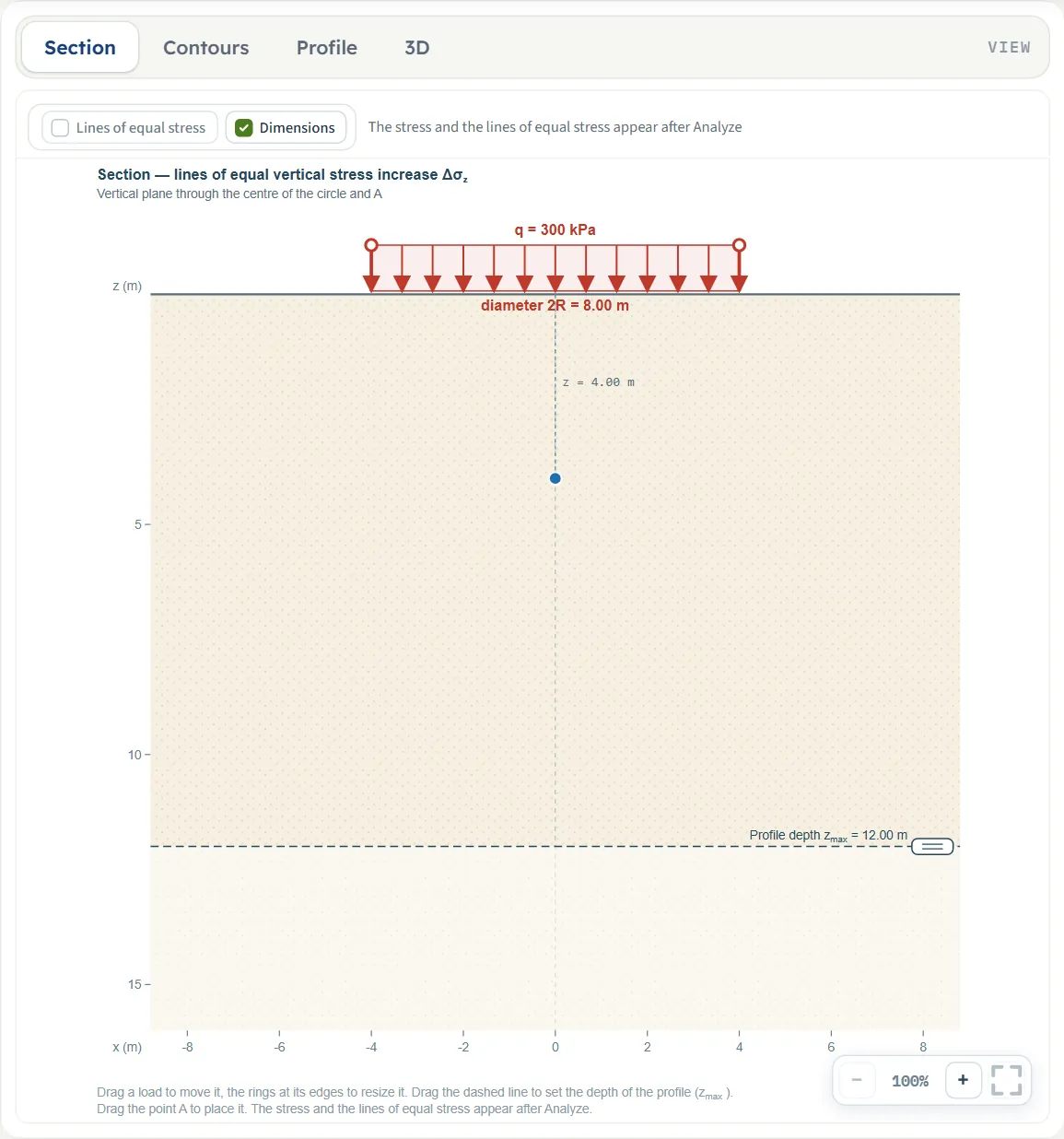
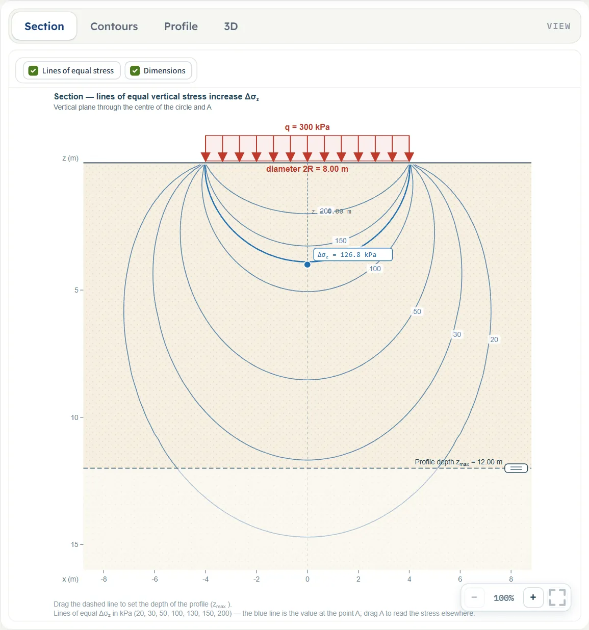
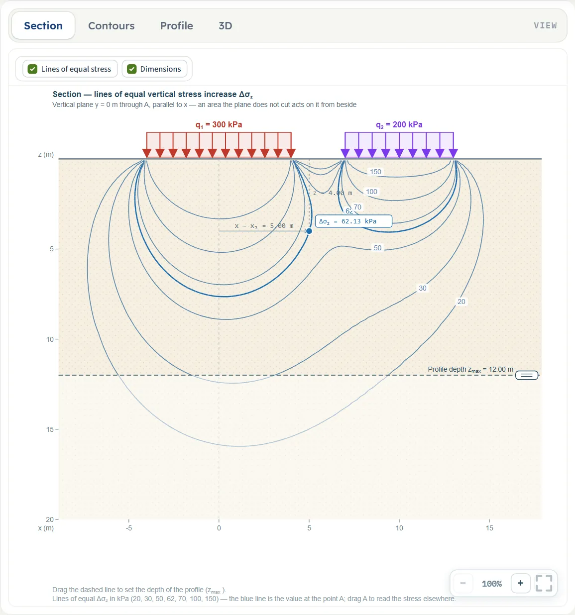
- Section is a vertical cross section with the loads on the ground, the point A, the dimensions and the dashed line of the profile depth. For one circle it is the plane through the centre of the circle and A; for a rectangle or for several areas it is the plane y = yA through A, parallel to x, and an area that the plane does not cut is drawn dashed with its distance from the plane. After Analyze it adds the lines of equal stress of Westergaard’s material and a label with Δσz at A.
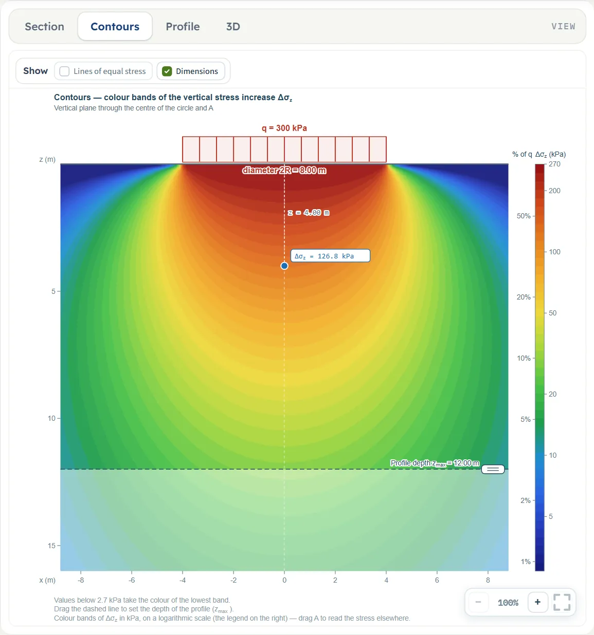
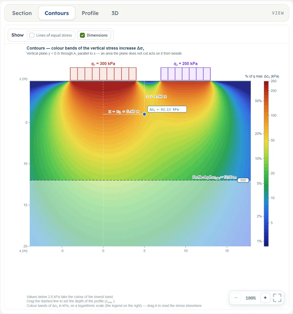
- Contours is the same section filled with colour bands of Δσz on a logarithmic scale, with a legend in kPa and in per cent of q.
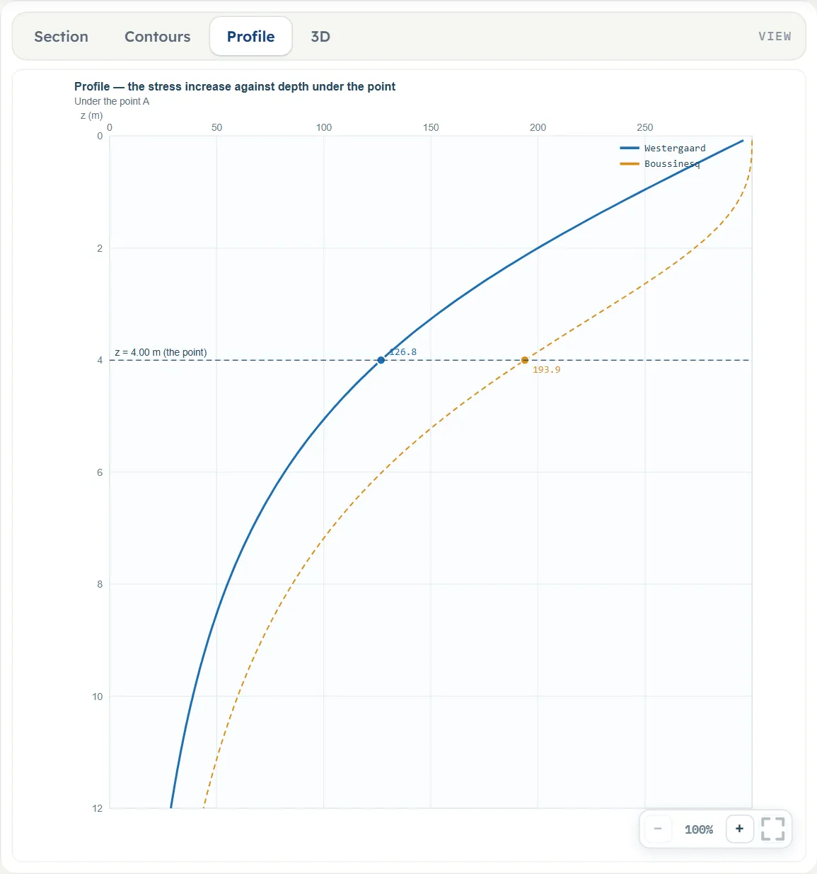
- Profile is the curve of Δσz against depth under A: Westergaard as a solid blue line and Boussinesq as a dashed orange line, with a marker and the value of each at the depth of A.
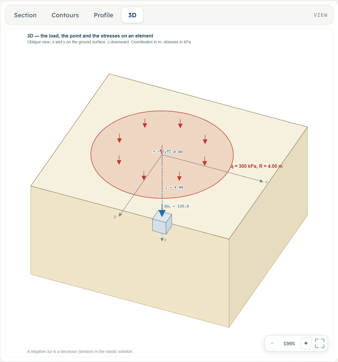
- 3D is an oblique view of the ground with the loaded areas on it, the axes x, y and z and a small element below A with the stress on it.
Before Analyze the drawings follow the inputs and say “The stress and the lines of equal stress appear after Analyze” (Section), “The colour contours of the stress appear after Analyze” (Contours), “The profile appears after Analyze.” (Profile) or “The stresses on the element appear after Analyze.” (3D).
The Show chips
Above the Section and the Contours drawings a bar has two chips: Lines of equal stress and Dimensions. In the Section view the lines chip is off and greyed out until you press Analyze, and then turns on; in Contours it is off by default, so that the lines can be laid over the colours. Dimensions is on by default in both. The Profile and 3D views have no chips.
Dragging on the drawing
Before Analyze the hints under the Section drawing say: “Drag the point A to place it. The stress and the lines of equal stress appear after Analyze.” and “Drag a load to move it, the rings at its edges to resize it. Drag the dashed line to set the depth of the profile (zmax).” After Analyze only the dashed-line sentence stays, with the note on the lines of equal stress and “drag A to read the stress elsewhere”. What each pull does, as the module runs it (pulls move in steps of 5 cm):
- One circle, Section. The drawing shows only the rings at its two edges: drag one to change the radius R; it stops at 0.1 m. The circle itself is moved in the 3D view.
- A rectangle, or several areas, Section. Drag the bar over an area to move it: xc follows the pointer. A rectangle also has a ring at each end: the edge you pull follows the pointer, the other edge stays where it is, so L and xc change together; the length stops at 0.1 m. A circle among several areas has no rings in the Section, only in 3D.
- 3D view. Drag the loaded area on the ground to move it along x and y together. A circle has rings at the ends of two diameters, one along x and one along y, and each sets the radius; a rectangle has rings at the ends of L and of B.
- The point A. Drag the blue point in the Section or the Contours view. The depth z stops at 0.05 m at the top and at the foot of the drawn frame at the bottom, and the horizontal position at the sides of the frame. With one circle A is placed by its distance from the centre of the circle, along the line from the centre through A, so x and y change together; otherwise x follows the pointer and y stays.
- The dashed line. Drag it up or down to set zmax; it stops at 0.5 m.
- Areas never overlap. A pull that would put one area on another stops at the last free place, where the two touch, and a message says “That would put loaded area 1 and loaded area 2 on top of one another — the value is kept as it was.”
- After Analyze the areas are locked: their rings and bars disappear and a pull changes nothing. The point A and the dashed line stay free, and so do the boxes x, y, z and zmax. There is no handle for A in the 3D view.
The 3D view has its own hint: “Drag a load over the ground to move it, the rings at its edges to resize it.”
Zoom
Each view has −, a percentage and + at the lower right, and a button that fits the whole drawing in the pane. The mouse wheel zooms as well. Zoom is a property of the drawing only: it is not saved with the model and does not change the report.
Entering the model, section by section
The Model tab has five sections: Model data, Loaded areas, Point A, Westergaard material and Depth profile. The four input sections (Loaded areas, Point A, Westergaard material, Depth profile) work as a set: opening one closes the others. Model data opens and closes on its own, and the module starts with Model data and Loaded areas open. Next and Back at the foot walk you through them, and Analyze waits below the last one. Where a unit is shown twice or three times, such as m · ft, the units are those of SI · kN, SI · tf and US in turn, and equal ones are merged. Defaults are shown in SI; in US the boxes show the converted values, for example 13.1234 ft for the 4 m radius.
Model data
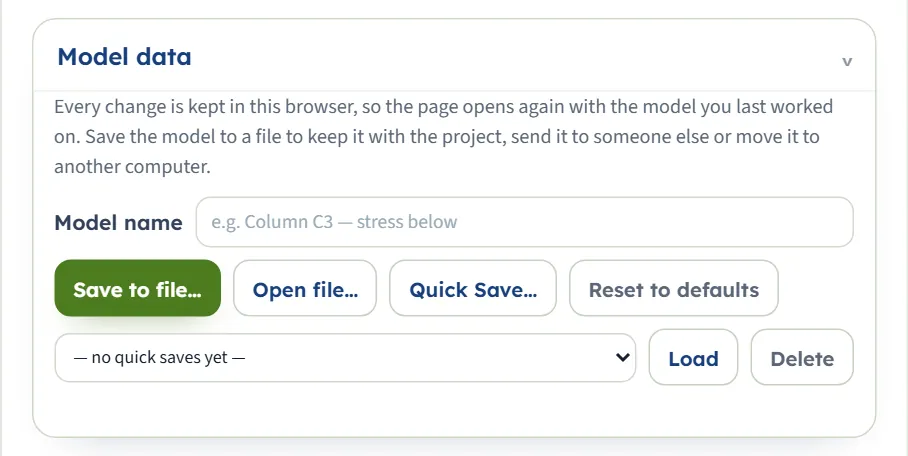
The first section holds the model name, Save to file…, Open file…, Quick Save… with its list and Load and Delete, and Reset to defaults. It works as described in the workspace guide.
Loaded areas
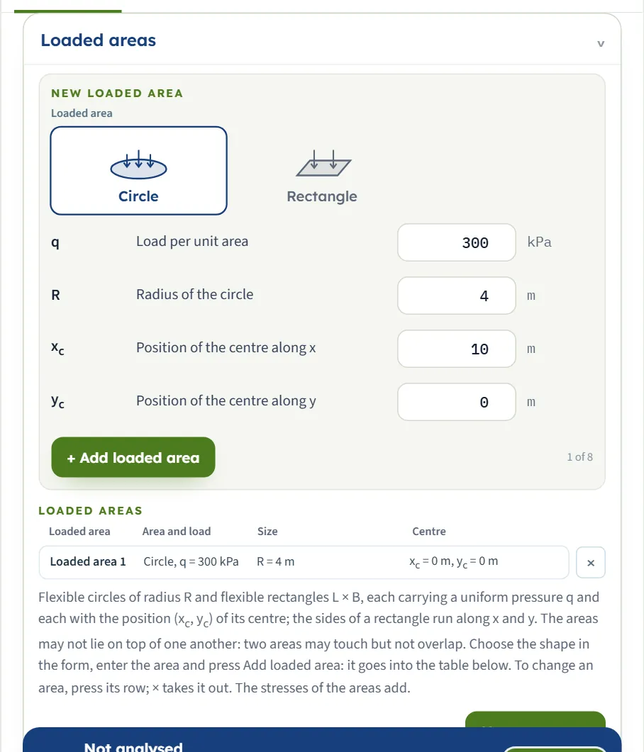
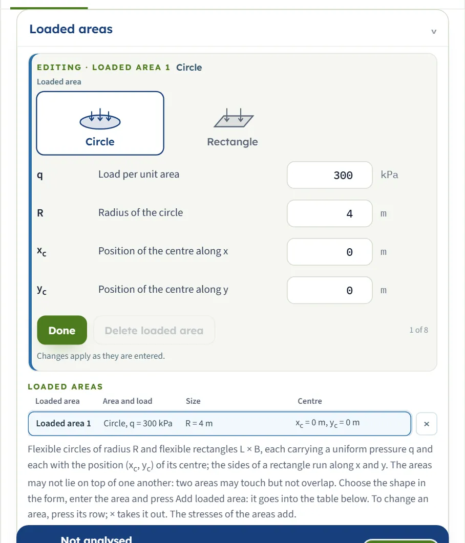
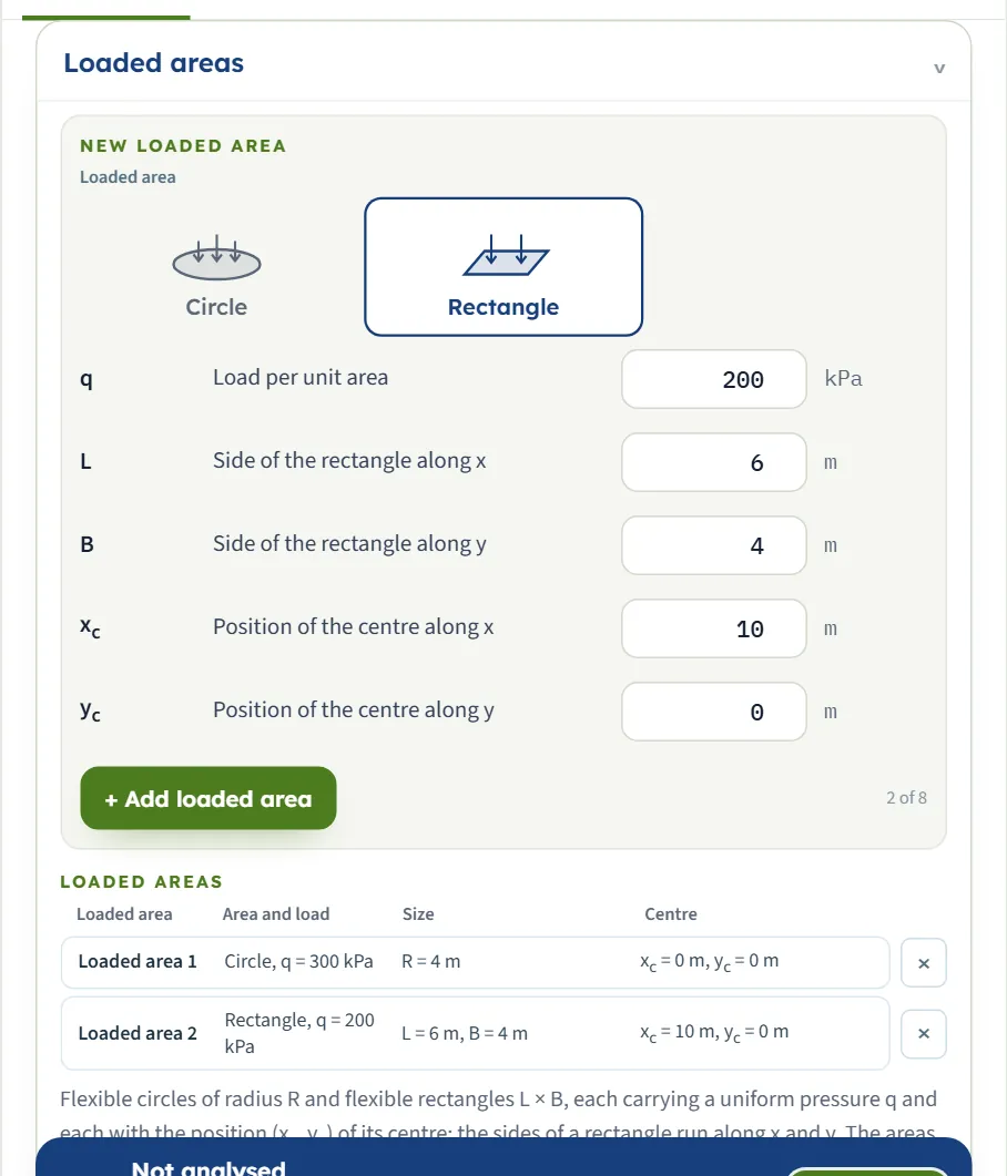
The section is a form over a table. The New loaded area form starts with the shape; Circle asks for R, Rectangle for L and B. + Add loaded area puts the area into the Loaded areas table, and a counter beside the button shows how many of the eight areas there are. The table lists each area with its shape and load, its size and its centre. Press a row to change that area in the form (the form then reads Editing · Loaded area 1 and offers Done and Delete loaded area; the note says that changes apply as they are entered), or press × to take an area out. The first area is already in the table when the module opens, and Delete loaded area and × are greyed out while it is the only one. A row that is being edited can change its shape with the buttons in the form: the first area becomes a rectangle of 3 m × 2 m when you press Rectangle.
| Field | What to enter |
|---|---|
| Loaded area (shape) — · default Circle | The buttons Circle and Rectangle, each with a small picture. Pressing the other one changes the fields below. |
| Load per unit area q kPa · t/m² · ksf · default 300 | The uniform pressure of the area on the ground. Zero or more. |
| Radius of the circle R m · ft · default 4 | At least 0.001 m. Shown when the shape is Circle. |
| Side of the rectangle along x L m · ft · default 3 | At least 0.001 m. Shown when the shape is Rectangle. |
| Side of the rectangle along y B m · ft · default 2 | At least 0.001 m. Shown when the shape is Rectangle. |
| Position of the centre along x xc m · ft · default 0 (area 1) · 10 (form) | Any value. The first area is centred at 0; the New loaded area form opens with 10. |
| Position of the centre along y yc m · ft · default 0 | Any value. |
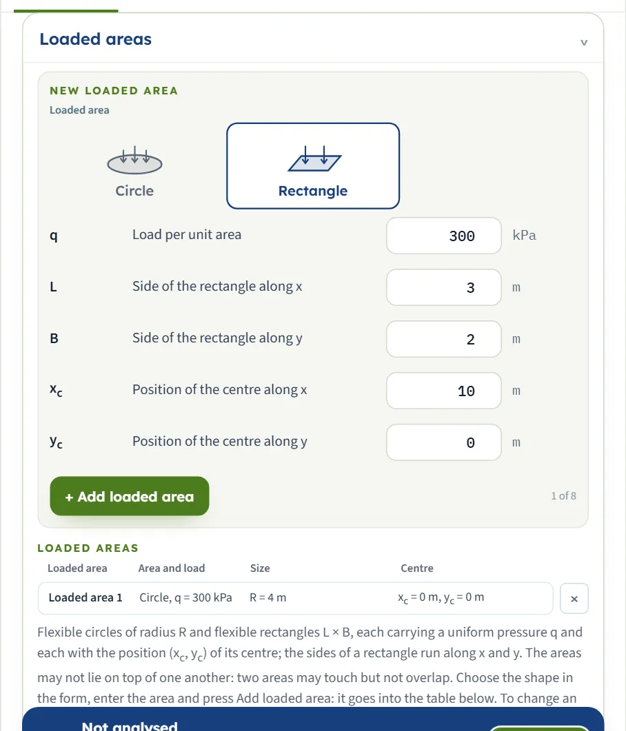
The areas may not lie on top of one another: two areas may touch but not overlap, whether they are two circles (the centres at least R1 + R2 apart), two rectangles or a circle and a rectangle. Adding or editing an area that would overlap another is refused (see Messages). The areas are listed in the order you add them, and their numbers name the results “From loaded area 1”, “From loaded area 2” and so on.
Point A
The three coordinates of the point where you want the stress. A is under the ground surface at (x, y) in the coordinates of the centres, at the depth z. The note in the section says that for a circle the closed form is for the centre, and other points are found by integrating the point-load solution; for a rectangle the closed form is for the corner, and other points by the corner rectangles. You can place A anywhere; you do not need to look for the centre or the corner.
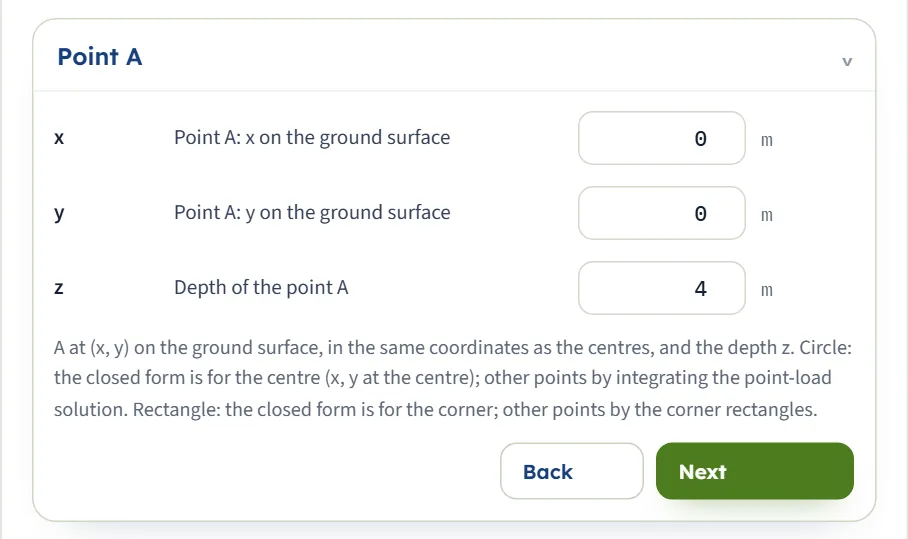
| Field | What to enter |
|---|---|
| Point A: x on the ground surface x m · ft · default 0 | Any value, in the same coordinates as the centres. |
| Point A: y on the ground surface y m · ft · default 0 | Any value, in the same coordinates as the centres. |
| Depth of the point A z m · ft · default 4 | At least 0.001 m below the ground surface. |
Westergaard material
One number, Poisson’s ratio μs of the soil between the rigid layers. The note says that this is Westergaard’s medium, soil between thin rigid horizontal sheets that prevent lateral strain, and that μs < 0.5.
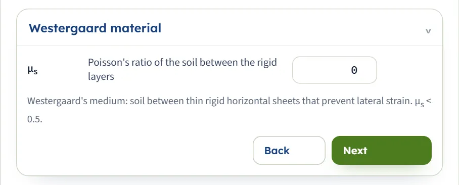
| Field | What to enter |
|---|---|
| Poisson’s ratio of the soil between the rigid layers μs — · default 0 | From 0 to 0.49. It sets the constant η = √[(1 − 2μs) / (2 − 2μs)]; η = 0.7071 at 0. |
Depth profile
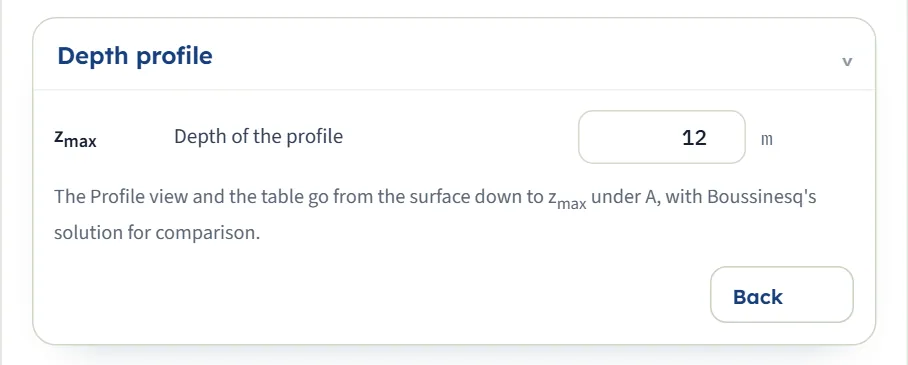
The depth down to which the Profile view and the table of the stress under A run.
| Field | What to enter |
|---|---|
| Depth of the profile zmax m · ft · default 12 | At least 0.1 m. The Profile view and the table under A go from the surface down to this depth, or to the depth of A if that is deeper. |
Choosing the shape, Poisson’s ratio and the comparison
Three decisions shape the answer: the shape of each area, how many areas there are, and the soil constant μs.
| Choice | Options | What it does |
|---|---|---|
| Shape (of each area) | Circle, Rectangle | A circle is given by its radius and a rectangle by its two sides along x and y. The sides of a rectangle always run along the axes. The circle of 4 m radius and the rectangle of 3 m × 2 m of the module’s forms put 126.8 kPa and 29.95 kPa on A at the same depth, with A at the centre of each. |
| Number of areas | 1 to 8 | Each is calculated alone and the stresses are added. See the next heading. |
| Poisson’s ratio μs | 0 to 0.49 | A larger μs gives a smaller η, so more of the load reaches A. |
Poisson’s ratio
For the example (one circle, R = 4 m, q = 300 kPa, A on the axis at z = 4 m) the module gives, with Boussinesq’s 193.9 kPa unchanged:
| μs | kPa | Δσz/q |
|---|---|---|
| 0 | 126.8 | 0.4226 |
| 0.2 | 143.3 | 0.4778 |
| 0.3 | 158.6 | 0.5286 |
| 0.45 | 213.4 | 0.7113 |
| 0.49 | 258.4 | 0.8613 |
At μs = 0 Westergaard’s value is about two thirds of Boussinesq’s here; as μs approaches 0.5 the stress below the load rises towards q and passes Boussinesq’s value, so the choice of μs matters. The module accepts values up to 0.49 only; the Calculations tab shows η for the value you enter.
Several areas and how they combine
The stress of each area is found as if it were alone, and the stresses are added. This works because the ground is elastic, so the stresses of separate loads add. The Results tab shows the total and, for two or three areas, the part from each.
- Coordinates are shared. The centres and A are in the same coordinates, so moving A and an area by the same amount changes nothing: the circle of the example moved to (6, 2) with A at (6, 2) gives 126.8 kPa again.
- Loads and shapes can differ. A circular tank and a rectangular slab can be put in one model, each with its own q.
- Far areas add little. With a second circle of 300 kPa and 4 m radius centred at 10 m, A at the origin gets 126.8 kPa from the first and 7.048 kPa from the second: 133.8 kPa in all. With the second area at 150 kPa the second part is 3.524 kPa.
- Between two areas. With A at x = 5 m, between the circles, each gives 47.13 kPa and the total is 94.25 kPa. The same circles touching (centres at 0 and 8 m) with A at x = 4 m, the touching point, give 69.51 kPa from each and 139.0 kPa in all.
Westergaard and Boussinesq side by side
Every result comes with Boussinesq’s value for the same loads and the same point, which is the answer for a ground without rigid layers. Boussinesq’s value does not depend on μs. Westergaard’s is lower than Boussinesq’s below the load at μs = 0, and it can be higher beside the load: with A at 8 m from the axis of the example the module gives 13.75 kPa against Boussinesq’s 12.54 kPa. Read both, and use the one that matches the ground you are modelling.
Which should I use?
- Circle or rectangle? Use the shape of the footprint. A tank, a silo or a circular footing is a circle; a slab or a rectangular footing is a rectangle. A footing of another shape is made of rectangles that touch, or can go to Influence chart for a homogeneous ground.
- One area or several? One when the load is uniform over a single footprint; several when pressures differ, or when there are gaps.
- A long strip or an embankment is not a good fit for circles and rectangles: use Vertical strip load or Embankment.
Analyze and read the results
Press Analyze. The bar changes to Analysed — the stress at the point calculated and says “The inputs are locked. Edit inputs clears the results; the unit system can still be changed. The point A stays free: drag it on the drawing or change its coordinates, and the stress there is calculated at once.” A message appears briefly, “Analysed — see the Results tab and the Calculations.” The module stays on the Model tab: open Results for the answer. The Section view now shows the lines of equal stress.
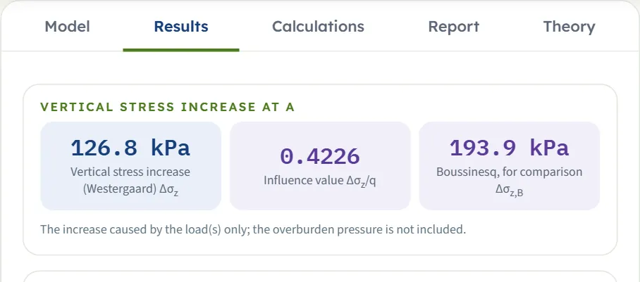
| Card | Symbol | The example |
|---|---|---|
| Vertical stress increase (Westergaard) | Δσz | 126.8 kPa |
| Influence value (one area only) | Δσz/q | 0.4226 |
| Boussinesq, for comparison | Δσz,B | 193.9 kPa |
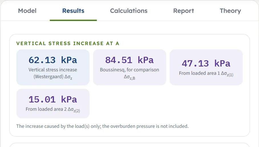
| From loaded area k (two or three areas) | Δσz(k) | the part of the total from area k |
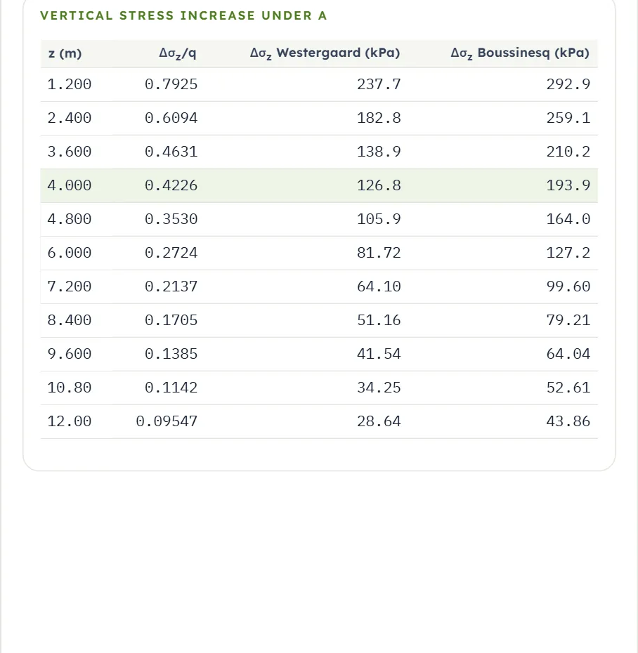
Below the cards a Values, step by step table lists the steps of the Calculations tab with their values, and the Vertical stress increase under A table gives z, Δσz for Westergaard and for Boussinesq, and, for one area, Δσz/q, at ten equal steps down to zmax (the first at zmax/10), with the row of A inserted and highlighted. With several areas the ratio column is left out; with four or more areas the cards show the total and Boussinesq’s value, and the part from each area is in the Calculations tab. If zmax is less than the depth of A, the table runs to the depth of A.
Using the numbers
- The result is an increase, not the total stress: add the overburden pressure of the soil above A for the total vertical stress.
- The influence value Δσz/q is the part of the surface pressure that reaches A. It is close to 1 just under the loaded area, and it falls with depth and with distance from the load. Beside a load the stress can first rise with depth: with A at x = 4 m, y = 3 m, which is 5 m from the centre of the example’s circle, the table gives 38.76 kPa at 1.2 m and 49.41 kPa at 2.4 m, then a slow fall.
- Values are rounded where they are drawn, so the last digit of a figure on the drawing can differ by one from the card.
- Change x, y, z or zmax after Analyze and everything follows at once; to change an area or μs, press Edit inputs, which unlocks them and clears the results.
- Changing the unit system after Analyze re-states the cards and the report without a new run. The drawings keep their labels in m and kPa.
Warnings and notes
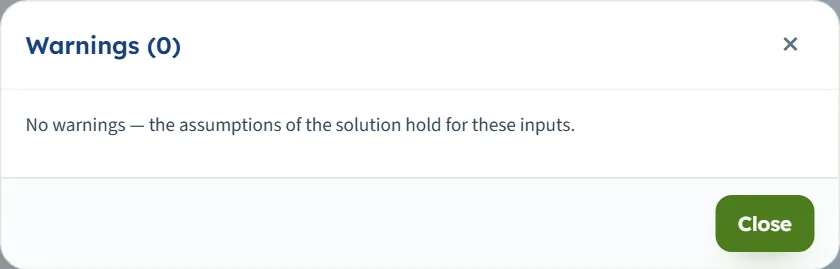
The bar carries a Warnings (0) button. It opens a window that says “No warnings — the assumptions of the solution hold for these inputs.” The runs of this manual, from the default to eight areas, gave no warning.
The Calculations tab, the report and the Theory tab
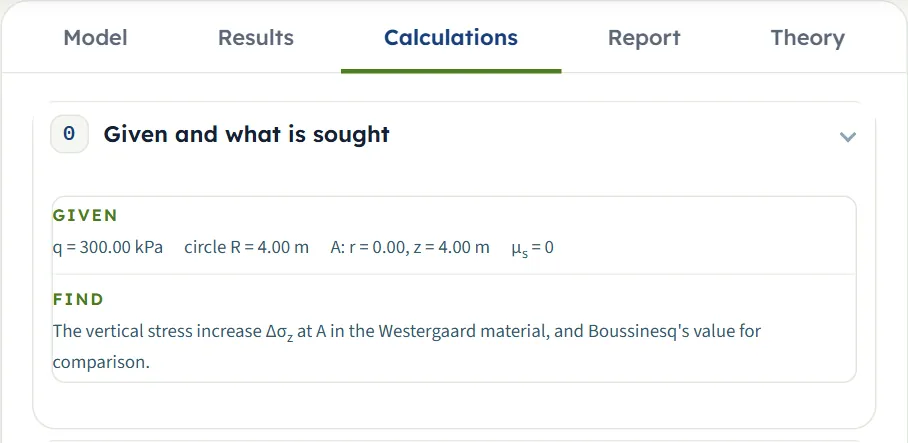
The Calculations tab opens with Given and what is sought: the loads, the point A and μs. Then it writes out the working in numbered steps, ending with the answer.
- The constant η — η = √[(1 − 2μs) / (2 − 2μs)] with your μs.
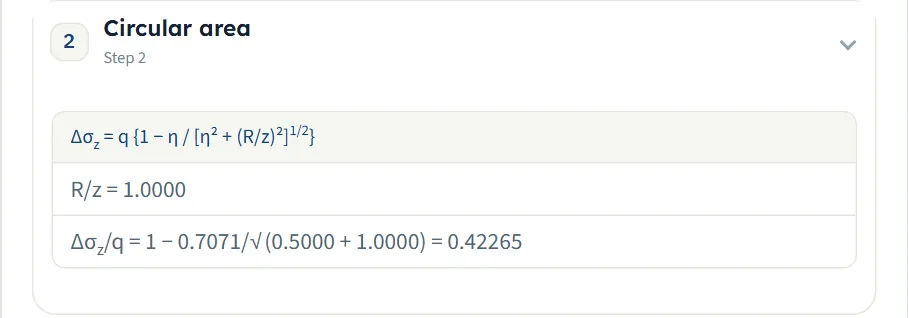
- The area — for one circle on its axis, Δσz = q {1 − η / √[η² + (R/z)²]} with R/z and Δσz/q; for a circle with A off its axis, the integral of the point-load solution with r, r/R, z/R and Δσz/q; for a rectangle, Iw for each of the four corner rectangles seen from A, listed with the corner, m, n, Iw and its sign, and their signed sum.
- Stress at A — Δσz = Δσz/q × q, Boussinesq’s value at the same point and the ratio of Westergaard’s to Boussinesq’s.
- Stress increase against depth — the same down the vertical line through A, as the table of the Results tab, with the row of A marked.
With several areas there is one step for each area, with its own geometry, then a Superposition step that adds the parts, then the depth table. In the corner rectangles m and n are the distances from A to the corner along x and y divided by z; Iw is the same when they swap.
For the example the first steps read:
The report
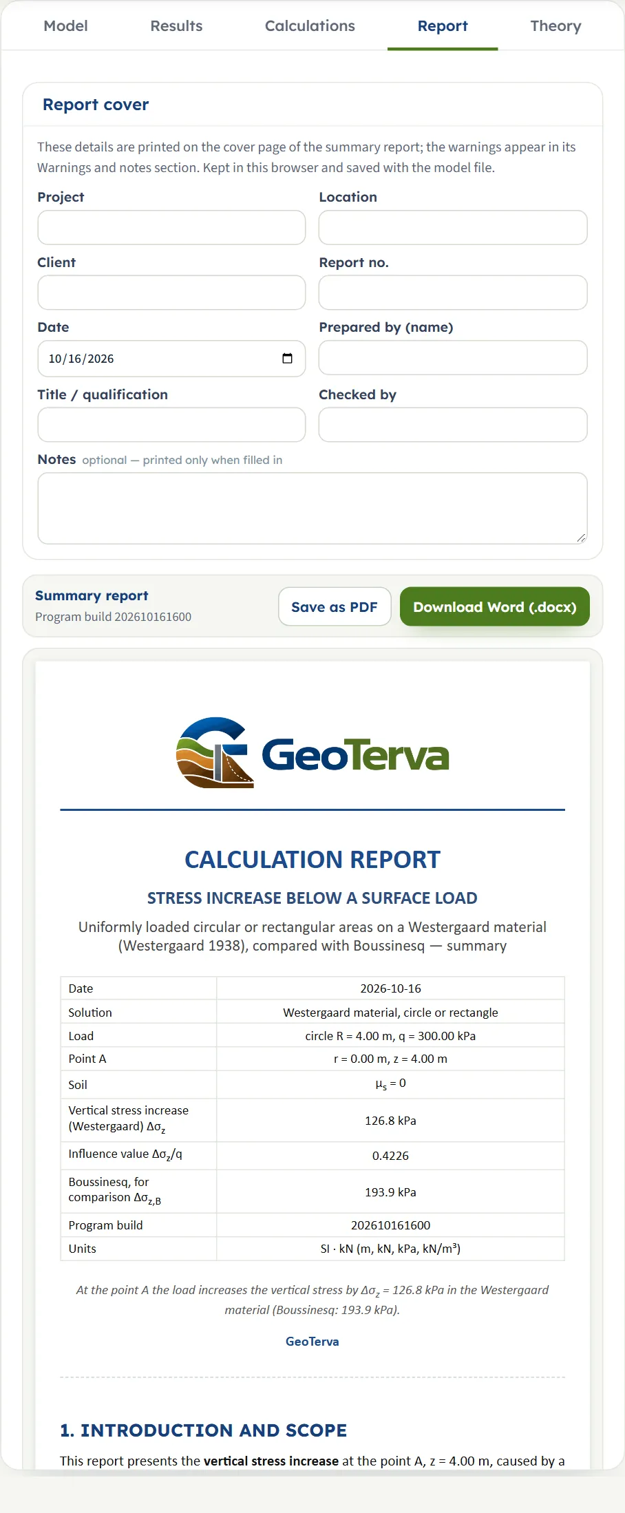
In the Report tab fill in the cover (project, location, client, report number, date, prepared by, title or qualification, checked by, and optional notes). The details are kept in this browser and saved with the model file. Save as PDF and Download Word (.docx) produce the summary report; the preview below the buttons is the report itself.
The report has six parts: 1 Introduction and scope, 2 Input data, 3 Calculation, 4 Results, 5 Summary and 6 References. It carries three drawings, the Section with the lines of equal stress, the Profile with both curves and the 3D view, and states the units used.
The Theory tab
The Theory tab has five sections: Scope, Circular area, Rectangular area, Worked example and References. Each opens when you click its title (Open all and Close all open or close them together). It gives the equations above, with three charts and three tables computed from them: the stress below the centre of a circle against R/z, Iw against m and n, and a worked example of Westergaard against Boussinesq below a circle.
Worked example: the module’s own example
The module opens on this example, so you can follow the numbers on your own screen.
| Section | Input | Value |
|---|---|---|
| Loaded areas | Loaded area 1 | Circle; q = 300 kPa; R = 4 m; centre (0, 0) |
| Point A | Position and depth | x = 0; y = 0; z = 4 m |
| Westergaard material | Poisson’s ratio | μs = 0 |
| Depth profile | Depth | zmax = 12 m |
Step 1: the constant
η = √[(1 − 0)/(2 − 0)] = 1/√2 = 0.7071.
Step 2: the circle
A is on the axis and R/z = 4/4 = 1.
Boussinesq’s value for the same circle is q{1 − 1/(1 + (R/z)²)3/2} = 300 × (1 − 0.3536) = 193.9 kPa, and the ratio of the two is 0.654, as the Calculations tab states. These are the three cards of the Results tab.
Doubling the radius or halving the depth gives the same R/z = 2 and so the same ratio, 0.6667, which is a hand check: R = 8 m with z = 4 m, and R = 4 m with z = 2 m, both give 200.0 kPa in the module (200.0 and 200.0 kPa).
A rectangle, below a corner
Take a square of 2 m × 2 m with q = 100 kPa and A below one corner, at (1, 1) with z = 2 m, μs = 0. Then m = n = 1, η² = 0.5, and
The module gives 11.61 kPa, an influence value of 0.1161, and Boussinesq’s 17.52 kPa. For the default rectangle of 3 m × 2 m, with A at its centre at 4 m depth, it gives 29.95 kPa (Boussinesq 45.96 kPa), and the Calculations tab lists the four corners with m = 0.3750, n = 0.2500 and Iw = 0.02496 each.
A circle and a rectangle together
Add a rectangle of q = 200 kPa, L = 6 m, B = 4 m centred at (10, 0) to the example and move A to x = 5 m. A is then 5 m from the centre of the circle, which is 1.25 radii, so the module integrates over the circle; it gives 47.13 kPa from the circle and 15.01 kPa from the rectangle, from the four corners (13, ±2) with signs + and (7, ±2) with signs −. With a third area, a circle of 100 kPa and 3 m radius at x = 20 m, the total is 62.51 kPa, and the third area adds only 0.3730 kPa. Without the third area the total is 62.13 kPa (Boussinesq 84.51 kPa). An independent numerical integration of Westergaard’s point load over each area gives the same values to the digits shown.
Other unit systems
The default example in SI · tf, with q = 30 t/m² (the other values unchanged), gives 12.68 t/m² and the influence value 0.4226. In US the default example, which is 6.266 ksf on a circle of 13.12 ft radius at 13.12 ft depth, gives 2.648 ksf: 126.8 kPa is 2.648 ksf. A check by hand with round US numbers: q = 6 ksf, R = 12 ft and A on the axis at z = 12 ft give R/z = 1, the same ratio 0.4226, so Δσz = 6 × 0.4226 = 2.536 ksf; the module gives 2.536 ksf (Boussinesq 3.879 ksf). For a rectangle, q = 2 ksf, 10 ft × 10 ft, A below a corner at 10 ft depth: m = n = 1, Iw = 0.1161, so Δσz = 0.2322 ksf; the module gives 0.2323 ksf.
How each input changes the answer
Values are in kPa. Each row changes one thing in the example (one circle of q = 300 kPa, R = 4 m at the origin, A at (0, 0, 4 m), μs = 0) and runs the module again, in SI · kN. The numbers are the ones the module gives, so you can reproduce any row; an independent numerical integration of Westergaard’s point load agrees with every row.
| Change | Westergaard | Boussinesq |
|---|---|---|
| The example Δσz/q 0.4226 | 126.8 | 193.9 |
| q = 600 kPa The stress is proportional to the load; the ratio is unchanged. Δσz/q 0.4226 | 253.6 | 387.9 |
| q = 100 kPa A third of the load, a third of the stress. Δσz/q 0.4226 | 42.26 | 64.64 |
| R = 2 m A smaller circle puts less on A. Δσz/q 0.1835 | 55.05 | 85.34 |
| R = 8 m The same R/z as z = 2 m with R = 4 m. Δσz/q 0.6667 | 200.0 | 273.2 |
| R = 20 m A wide circle: the ratio rises towards 1. Δσz/q 0.8600 | 258.0 | 297.7 |
| z = 0.5 m Near the surface the stress approaches q. Δσz/q 0.9120 | 273.6 | 299.4 |
| z = 2 m The stress falls with depth. Δσz/q 0.6667 | 200.0 | 273.2 |
| z = 8 m The same R/z as R = 2 m at 4 m depth. Δσz/q 0.1835 | 55.05 | 85.34 |
| z = 16 m Deep below the load the stress is a small part of q. Δσz/q 0.05719 | 17.16 | 26.08 |
| μs = 0.3 A larger μs puts more stress on A; Boussinesq’s value does not change. Δσz/q 0.5286 | 158.6 | 193.9 |
| μs = 0.49 The largest value the module accepts: Westergaard’s stress passes Boussinesq’s. Δσz/q 0.8613 | 258.4 | 193.9 |
| A 2 m from the axis (x = 2 m) Inside the circle but off its axis. Δσz/q 0.3732 | 112.0 | 168.7 |
| A below the edge (x = 4 m) About 55 per cent of the stress on the axis. Δσz/q 0.2317 | 69.51 | 99.67 |
| A 8 m from the axis (x = 8 m) Beside the load Westergaard’s value is the larger of the two. Δσz/q 0.04583 | 13.75 | 12.54 |
| x = 4 m, y = 3 m The distance from the centre is 5 m: the same as x = 5 m, y = 0. Δσz/q 0.1571 | 47.13 | 64.13 |
| x = −4 m The same as x = +4 m: the circle is symmetric about its centre. Δσz/q 0.2317 | 69.51 | 99.67 |
| Area 1 a rectangle, 3 m × 2 m A smaller footprint than the circle; A at its centre. Δσz/q 0.09983 | 29.95 | 45.96 |
| Area 1 a rectangle, 8 m × 8 m A square of side 8 m, 64 m² against the circle’s 50 m². Δσz/q 0.4646 | 139.4 | 210.3 |
| Rectangle 3 m × 2 m, A below a corner (x = 1.5, y = 1) The stress under a corner is much less than under the centre. Δσz/q 0.06900 | 20.70 | 32.12 |
| Rectangle 3 m × 2 m, A at x = 5 m A is 3.5 m from the edge: a small stress. Δσz/q 0.01540 | 4.619 | 5.771 |
Several areas, SI · kN, A at (0, 0, 4 m) unless stated, one change at a time from the example (area 2 added with the values shown):
| Added | Total (kPa) | Parts (kPa) |
|---|---|---|
| Circle: 300 kPa, R = 4 m, centre (10, 0) A on the first circle’s axis | 133.8 | 126.8 + 7.048 |
| Circle: 150 kPa, R = 4 m, centre (10, 0) Half the load, half the part | 130.3 | 126.8 + 3.524 |
| Circle: 300 kPa, R = 4 m, centre (0, 8) 8 m away along y, touching; A on the first axis | 140.5 | 126.8 + 13.75 |
| Rectangle: 300 kPa, 3 m × 2 m, centre (10, 0) A on the circle’s axis | 127.5 | 126.8 + 0.7463 |
| Circle: 300 kPa, R = 4 m, centre (10, 0) A at x = 5 m, midway | 94.25 | 47.13 + 47.13 |
| Circle: 300 kPa, R = 4 m, centre (10, 0) A at x = 10 m, on the second axis | 133.8 | 7.048 + 126.8 |
The pattern follows the equations. The stress is proportional to q; for a circle on its axis it depends on R/z only, so doubling every length leaves the ratio unchanged; it falls with depth and with distance from the load, and it rises with μs. The depth of the profile zmax changes the table and the Profile view but not the stress at A: 126.8 kPa with zmax = 6 m and 126.8 kPa with zmax = 2 m; as that is less than the depth of A, the table runs to the depth of A.
Messages: when the module stops, and what it notes
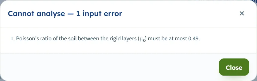
The module checks the numbers it needs before it calculates. When an input cannot be used, press Analyze and a window titled Cannot analyse — 1 input error (or 2 input errors …) lists each message, and a box with an out-of-range value is marked in red; an empty box is named in the list only. Nothing is calculated.
| When | Message and what to do |
|---|---|
| z is 0 | “Depth of the point A (z) must be at least 0.001 m.” Enter a depth of at least 0.001 m. |
| μs is 0.5 or more | “Poisson's ratio of the soil between the rigid layers (μs) must be at most 0.49.” Enter a value from 0 to 0.49. |
| μs is negative | “Poisson's ratio of the soil between the rigid layers (μs) must be at least 0.” Enter 0 or more. |
| q is negative | “Load per unit area of area 1 (q1) must be at least 0 kPa.” Enter zero or a positive load. |
| R is 0 | “Radius of circle 1 (R1) must be at least 0.001 m.” Enter a radius of at least 0.001 m. |
| A side of a rectangle is 0 | “Side of rectangle 1 along x (L1) must be at least 0.001 m.” Enter a side of at least 0.001 m. |
| zmax is 0 | “Depth of the profile (zmax) must be at least 0.1 m.” Enter a depth of at least 0.1 m. |
| A box is empty | “Radius of circle 1 (R1) is missing.” or “Poisson's ratio of the soil between the rigid layers (μs) is missing.” Fill the box or take the area out. |
| A new area would overlap another | A message appears briefly: “The new loaded area would lie on loaded area 1 — they cannot overlap. Give it another position or width.” The area is not added. |
The messages use the numbered names of the areas, such as “area 1”, “circle 1”, “rectangle 1” and “q1”, even when there is only one area, and the limits in the units of the unit system chosen. Two wrong values are listed together: L = 0 and μs = 0.5 give “Cannot analyse — 2 input errors” with both messages. When you type a position or size into an area already in the table and it would put two areas on one another, a message appears briefly: “That would put loaded area 1 and loaded area 2 on top of one another — the value is kept as it was.” and the value stays as it was. At eight areas + Add loaded area is greyed out and the counter reads 8 of 8.
Notes and warnings
With every input inside its limits the module calculates, and the Warnings window reads “No warnings — the assumptions of the solution hold for these inputs.” A load of zero is accepted and gives 0 kPa, with a dash for the influence value. Small and large values are accepted too: a radius of 0.001 m gives 0.00001875 kPa at A, and with q = 1,000,000 kPa and R = 1000 m the module gives 997,172 kPa, an influence value of 0.9972. A point far from the load is accepted: x = −30 m gives 0.2530 kPa.
Good practice and common mistakes
- Decide whether the ground is Westergaard’s material. The module is for soil that is stiffened by thin rigid layers; for a homogeneous ground use Boussinesq’s modules, or read the Boussinesq card and column of this module.
- Choose μs with care. It changes the answer a great deal: for the example 126.8 kPa at 0, 158.6 kPa at 0.3 and 258.4 kPa at 0.49. The module opens with 0.
- Enter a pressure, not a force. q is a load per unit area. A total load Q on a circle is Q/(πR²).
- Mind the coordinates. Centres and A are in the same coordinates. A rectangle’s sides run along x and y; swap L and B to turn it.
- Do not overlap areas. Areas may touch but not lie on one another; to describe a stepped load, split it into areas that meet.
- Add the overburden. The result is the stress increase; for the total vertical stress add the soil weight above A.
- Read the profile as well as the point. Beside a load the stress can rise with depth before it falls; the Profile view and the table show it.
- Place A with the drawing, then type exact values. Dragging moves in 5 cm steps; type the coordinates when you need a given place.
- Check the units after switching the system: type values in the units shown beside the boxes.
- Keep a record. The report is the record of an analysis; use Quick Save… or Save to file… to keep the model.
Frequently asked questions
What is Westergaard’s material?
An elastic soil that is stiffened by thin, rigid horizontal layers, which stop it spreading sideways. The soil between the layers has Poisson’s ratio μs, which the module asks for. The vertical stress below a load is then given by Westergaard’s solution instead of Boussinesq’s.
How is the stress below a loaded area calculated?
The module integrates Westergaard’s point load over the area. Below the centre of a circle it is Δσz = q{1 − η/√[η² + (R/z)²]}, and below a corner of a rectangle Δσz = q Iw; any other point is found by integrating over the circle or by four signed corner rectangles. For the module’s example it gives 126.8 kPa, with Boussinesq’s 193.9 kPa beside it.
What does Poisson’s ratio do?
It sets η = √[(1 − 2μs)/(2 − 2μs)]. A larger μs puts more stress on a point below the load: for the example 126.8 kPa at 0, 158.6 kPa at 0.3 and 258.4 kPa at 0.49. Boussinesq’s value does not depend on it. The module accepts 0 to 0.49.
Why is there a Boussinesq value as well?
It is the answer for the same loads on a homogeneous elastic ground, given for comparison on the cards, in the table and as the dashed curve of the Profile view. At μs = 0 Westergaard’s value below a load is lower than Boussinesq’s.
Does the result include the weight of the soil?
No. It is the increase caused by the loaded areas only. Add the overburden pressure of the soil above A for the total vertical stress.
How many areas can I add, and can they overlap?
Up to eight, each a circle or a rectangle with its own q and size. They may touch but not overlap; the module refuses an area that would lie on another. The stresses of the areas add.
Can I put A anywhere?
Yes. A is at (x, y) on the ground and at the depth z, in the coordinates of the centres. You do not have to place it at the centre of a circle or the corner of a rectangle; the module integrates for other points.
Can I drag the areas and the point on the drawing?
Yes. In the Section view drag the rings at the edges of a circle or the ends of a rectangle to resize it, and the bar over an area (with a rectangle or several areas) to move it; in the 3D view drag the area on the ground. Drag the blue point to place A and the dashed line to set the depth of the profile; they move in 5 cm steps. After Analyze the areas are locked, but A and the dashed line stay free.
What do the lines of equal stress show?
Each line joins the points of the section with the same Δσz, labelled in kPa; the line through A is blue. Switch them on and off with the Lines of equal stress chip. The Contours view shows the same stress as colour bands on a logarithmic scale.
What values does the module accept?
q zero or more, R, L and B at least 0.001 m, z at least 0.001 m, μs from 0 to 0.49, zmax at least 0.1 m, and x, y, xc and yc any value. Anything else stops the analysis with a message that names the value.
Which units does it use, and what are the units of the answer?
SI · kN, SI · tf or US, switchable in the header at any time, even after Analyze. Stresses are in kPa, t/m² or ksf and lengths in m or ft. The default example gives 126.8 kPa, 12.68 t/m² with q = 30 t/m², or 2.648 ksf.
Does the module remember my inputs, and what does the report contain?
Every change is kept in the browser, and the page opens again on the model you last worked on, including its analysed state. Reset to defaults brings back the example; Save to file and Quick Save keep copies. The report has a cover with your project details and the answer, then six parts: introduction and scope, input data, the calculation step by step, results, summary and references, with the section, profile and 3D drawings. It is saved as a PDF or a Word file once the model is analysed.