

What the module calculates
Rankine gives the earth pressure on a vertical wall from a level backfill, by Rankine’s theory (1857): the pressure diagram on the back of the wall, its resultant per unit length of wall, and the height above the base at which the resultant acts. You choose the active state, when the wall moves away from the soil, or the passive state, when it is pushed into it. The backfill is entered in layers, each with its own unit weights and strength, with a uniform surcharge and a water table.
The pressure at a depth follows from the vertical effective stress σ′v there and the coefficient of the layer:
q is the uniform surcharge, γi and Hi are the unit weight and thickness of each layer above the depth z (below the water table the effective unit weight γsat − γw is used), and u is the pore-water pressure below the water table zw. The force is the area of the pressure diagrams, and its line of action is the centroid of those areas about the base.
What you can describe
- A vertical wall of height H with a level backfill; the wall face is taken as frictionless.
- The state: Active or Passive.
- Up to six layers of backfill from the top down, each drained (with c′ and φ′) or undrained (with cu and φu = 0, so that Ka = Kp = 1).
- A uniform surcharge q over the whole backfill surface, and a water table behind the wall, or none.
- In the active state, how a cohesive backfill is treated near the top: with tension cracks or as the theoretical Rankine pressure.
The module gives the force from the soil, the force from the water, their total, the height of the total above the base, and the depth of the tension zone when there is one. It draws the section, the pressure diagram and a 3D view, writes out the working, and prepares a PDF or Word report.
Which module for which wall
- A wall that cannot move (a basement wall, a braced wall) keeps the soil at rest: use At rest.
- A backfill that slopes up behind the wall: use Rankine, sloping backfill.
- Friction on the back of the wall, a battered wall or a sloping backfill by the wedge theory: use Coulomb.
- The active force in an earthquake: Mononobe–Okabe; the passive resistance on a curved failure surface: Passive, log spiral; the passive force in an earthquake: Passive, earthquake.
- The module takes one uniform surcharge. For a point, line, strip, triangular, ramp or area load on the backfill, use the Surcharge loads manuals and add the result to the pressure from this module.
Before you start: what you need
Have these ready from your design and your ground investigation:
| What | Where it comes from | Notes |
|---|---|---|
| The wall height H | Your design | From the top of the backfill to the base of the wall. At least 0.1 m. |
| The state | How the wall moves | Active when the wall moves away from the soil enough for the soil to reach its limit state; passive when the wall is pushed into the soil. |
| The layers of backfill | Boring logs and tests | For each layer from the top down: thickness (not for the last one, which runs to the base), unit weight, saturated unit weight if there is water, and the strength: φ′ and c′, or cu for an undrained layer. |
| The water table | Groundwater readings | The depth zw below the top of the wall, behind the wall; or none. |
| The surcharge q | Your design loading | A load per unit area on the whole backfill surface. Zero or more. |
Quick start in seven steps
- Open the module and choose the units
Open Rankine from the Lateral Earth Pressure family. Pick SI · kN, SI · tf or US in the header; you can change it at any time.
- Describe the wall
In Wall, choose Active or Passive, type the height H and the surcharge q. In the active state also choose how a cohesive backfill is treated near the top: Tension cracks — σ′ₐ = 0 above z₀ or No cracks — theoretical Rankine.
- Enter the soil layers
In Soil layers fill the New layer form and press + Add layer. The layer goes to the bottom of the table. Press a row of the table to change it; × takes it out.
- Enter the groundwater
In Groundwater choose Present and type the depth zw, or choose None.
- Press Analyze
Press Analyze at the foot of the Model tab. The bar reads Analysed and the inputs lock. Press Pressure above the drawing to see the diagram on the wall.
- Read the answer
The Results tab gives the force, its line of action above the base, the parts from the soil and from the water, the coefficient of each layer and the stresses behind the diagram.
- Take the working and the report
The Calculations tab writes out the steps with your numbers. The Report tab saves a PDF or a Word file.
The screen: section, pressure and 3D
The layout is the one every GeoTerva module shares, described in the workspace guide. For this module the drawing has three views, chosen with the buttons above it:
- Section is the wall, the surcharge, the soil layers with their unit weights and strength, the water table and the dimensions. It follows your inputs; after Analyze it adds the coefficient Ka (or Kp) of each layer.
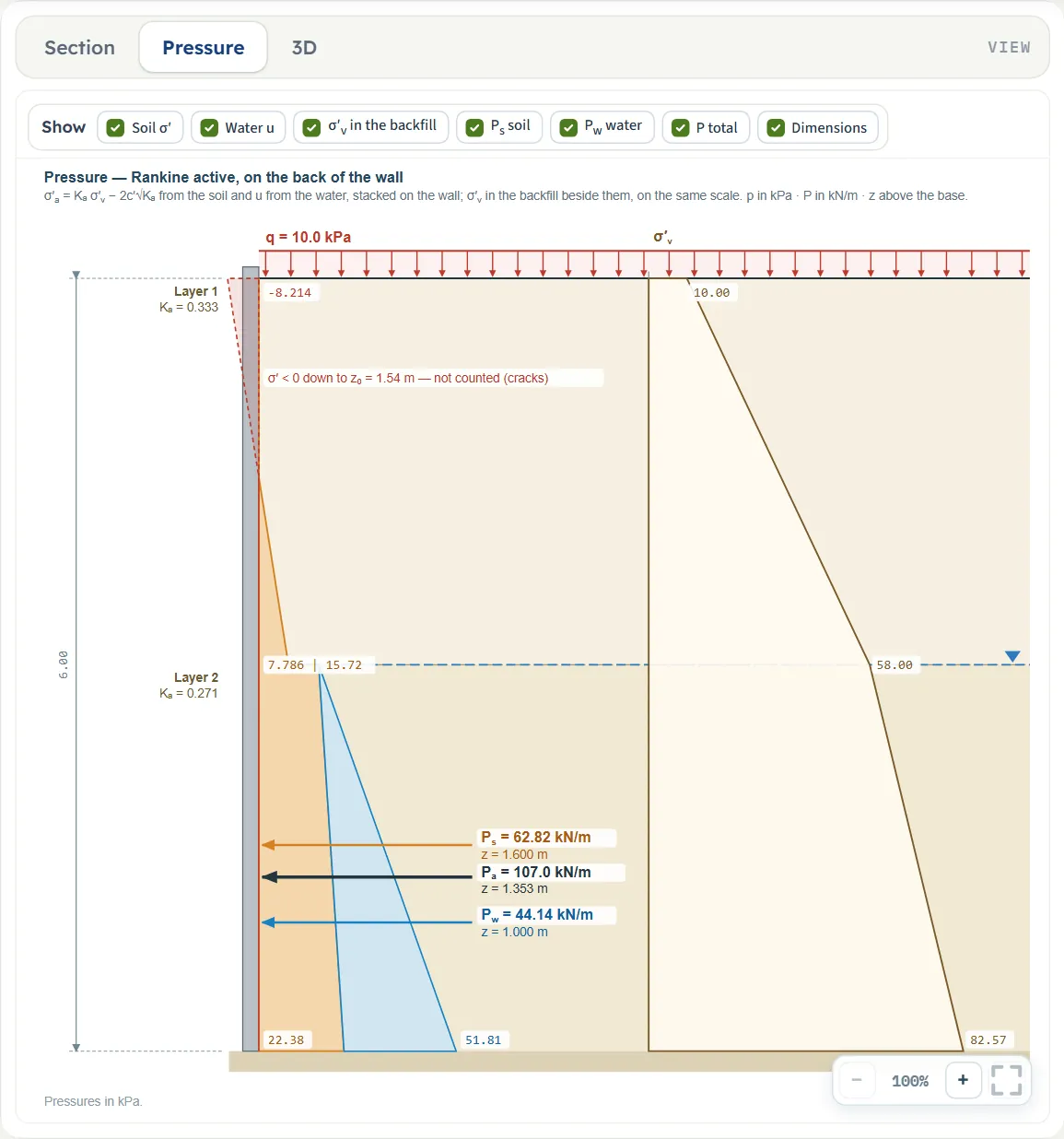
- Pressure is the pressure on the back of the wall. Before Analyze it shows the geometry only; after it, the soil pressure σ′ and the water pressure u stacked on the wall, the tension zone of a cohesive soil on the other side of the wall, the resultants of the soil, of the water and in total at their heights above the base, and the vertical effective stress σ′v in the backfill beside it, on the same scale.
- 3D is a length of the wall with the backfill on the right. After Analyze it shows the pressure prism on the wall face, the resultant and the pressure at the base.
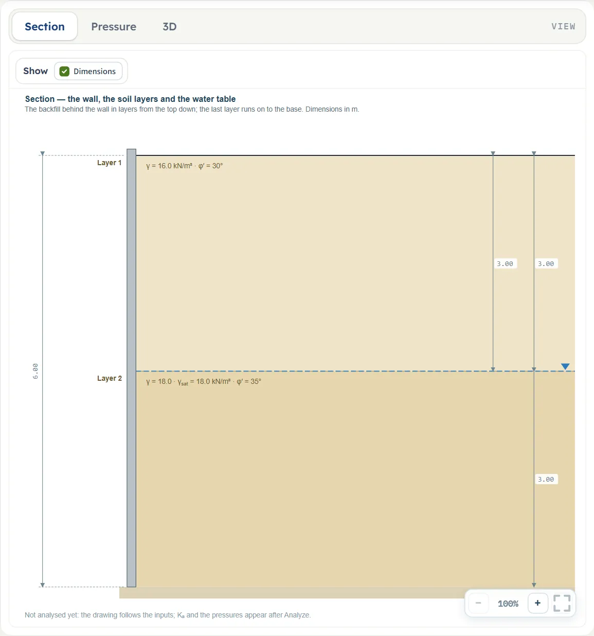
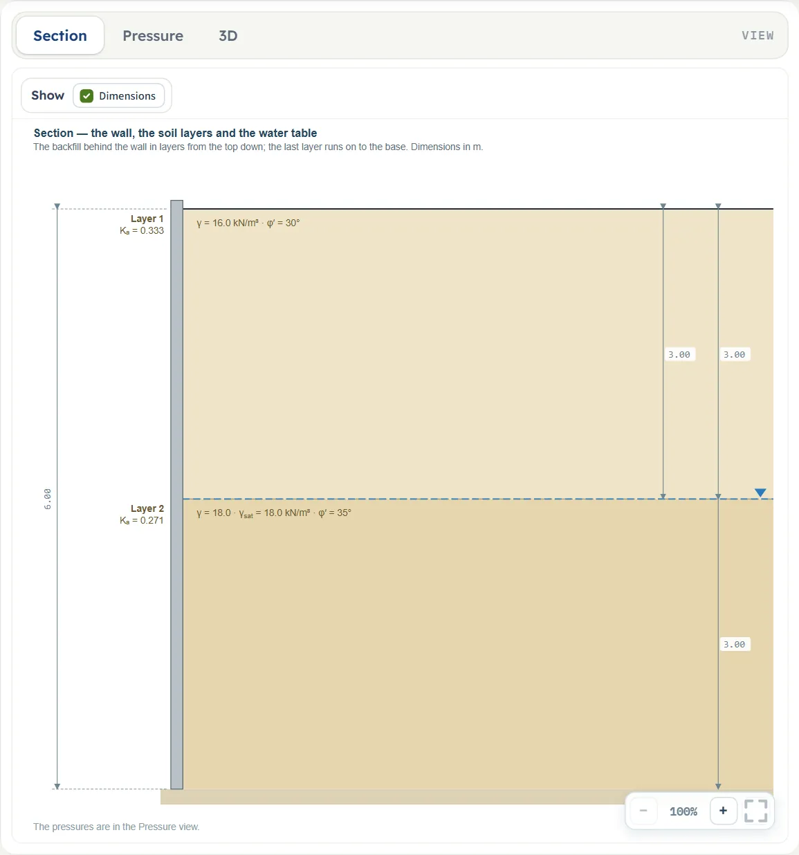
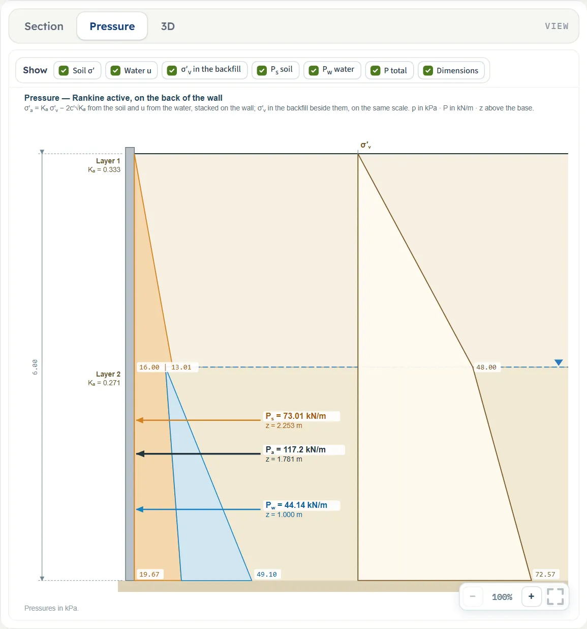
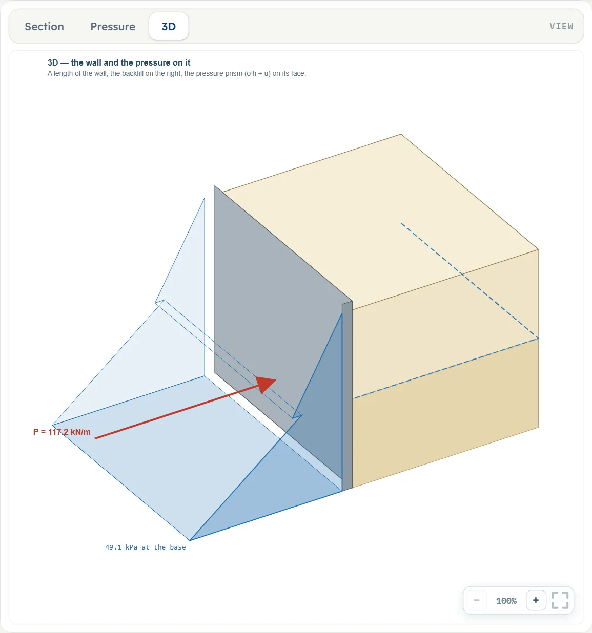
The Show chips
Above the drawing a Show bar switches parts of the drawing on and off. Dimensions is the only chip of the Section view and is on by default. The Pressure view has seven: Soil σ′, Water u, σ′v in the backfill, Ps soil, Pw water, P total and Dimensions. Before Analyze the pressure chips are unchecked and the bar says “The pressures and the resultant appear after Analyze”; after it they are all on. The 3D view has no chips.
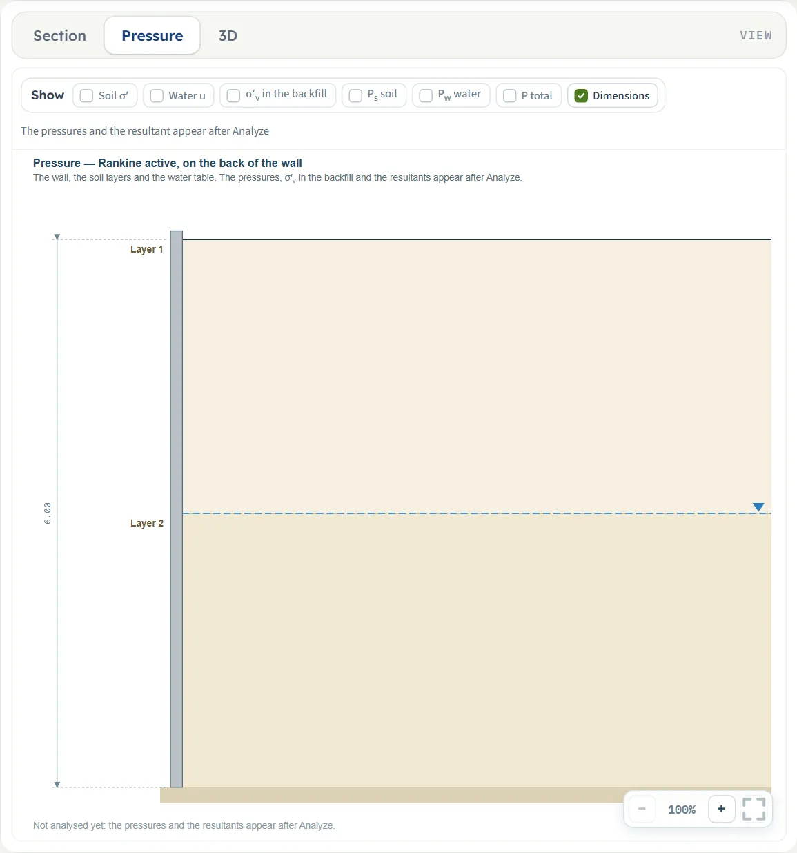
Zoom
Each view has −, a percentage and + at the lower right, and a button that fits the whole drawing in the pane. The mouse wheel zooms as well.
Entering the model, section by section
The Model tab has four sections: Model data (names, files and quick saves, the same in every module), Wall, Soil layers and Groundwater. Each opens when you click its title; Next and Back at the foot walk you through them, and Analyze waits below the last one. The tables list every field with its symbol, the unit in each unit system and its default. Where a unit is shown twice or three times, such as m · ft, the units are those of SI · kN, SI · tf and US in turn, and equal ones are merged. Defaults are shown in SI; in US the boxes show the converted values, for example 19.685 ft for the 6 m wall.
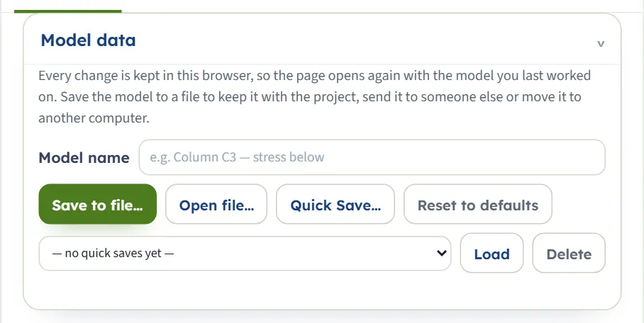
Model data
The first section holds the model name, Save to file…, Open file…, Quick Save… with its list and Load and Delete, and Reset to defaults. It works as described in the workspace guide. Reset returns the example at once.
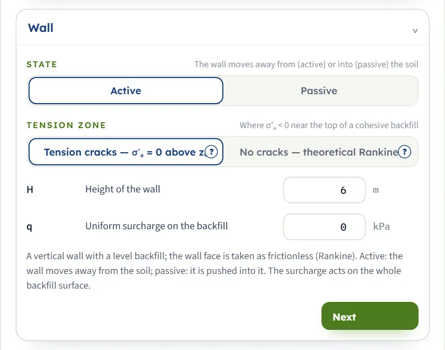
Wall
Two choices and two numbers. State has the buttons Active and Passive. Tension zone has Tension cracks — σ′ₐ = 0 above z₀ and No cracks — theoretical Rankine, each with a (?) that opens a help window; it is shown in the active state only. The note under the fields says that the wall is vertical, the backfill level, the wall face frictionless and that the surcharge acts on the whole backfill surface.
| Field | Unit | Default | What to enter |
|---|---|---|---|
| Height of the wall H | m · ft | 6 | From the top of the backfill to the base of the wall. At least 0.1 m. |
| Uniform surcharge on the backfill q | kPa · t/m² · ksf | 0 | A load per unit area on the whole backfill surface. Zero or more; it adds to σ′v at every depth. |
Soil layers
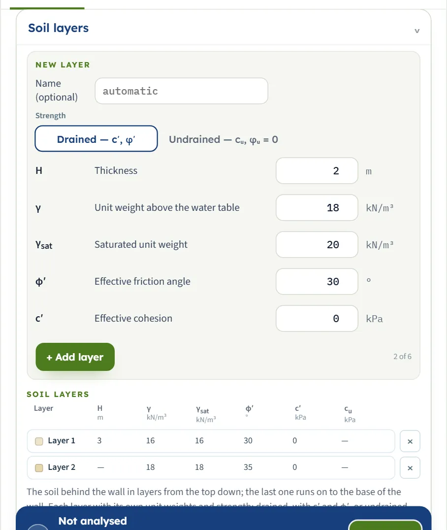
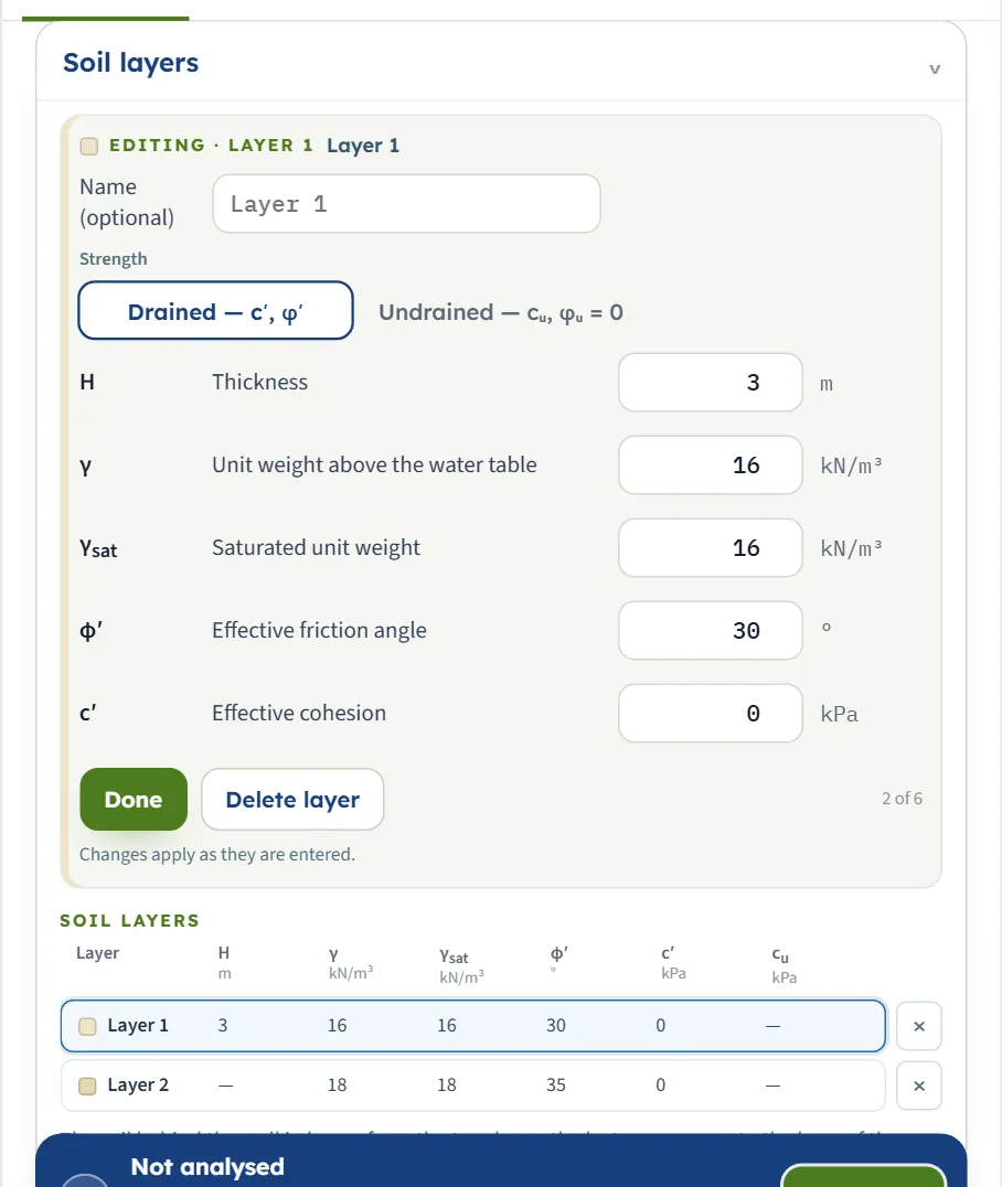
The section is a form over a table. The New layer form takes the name, the strength (Drained — c′, φ′ or Undrained — cᵤ, φᵤ = 0) and the values of one layer. + Add layer puts it at the bottom of the table, and a counter beside the button shows how many of the six layers there are. The Soil layers table lists every layer with its thickness, unit weights and strength, and a swatch of the colour the layer has on the drawing. Press a row to change that layer in the form (the form then reads Editing · Layer 1 and offers Done and Delete layer; the note says that changes apply as they are entered), or press × to take a layer out. The soil is entered from the top down, and the last layer runs on to the base of the wall.
| Field | Unit | Default | What to enter |
|---|---|---|---|
| Name | — | automatic | Shown on the drawing and in the tables. Leave it blank for Layer 1, Layer 2 … (optional) |
| Thickness Hi | m · ft | 2 (form) | From the top of the wall down. At least 0.01 m. The last layer has no thickness: it runs on to the base of the wall, and its row of the table shows a dash. |
| Unit weight above the water table γ | kN/m³ · t/m³ · pcf | 18 (form) | At least 1. Used above the water table, or everywhere when there is no water table. |
| Saturated unit weight γsat | kN/m³ · t/m³ · pcf | 20 (form) | At least 1, and above the unit weight of water (9.81 kN/m³) for a layer that reaches below the water table. The effective unit weight below the water table is γsat − γw. Shown when the water table is present. |
| Effective friction angle φ′ | ° | 30 (form) | From 0° to 50°. It gives Ka or Kp of the layer. Shown when the strength of the layer is Drained. |
| Effective cohesion c′ | kPa · kg/cm² · psf | 0 (form) | Zero or more. Shown when the strength of the layer is Drained. |
| Undrained shear strength cu | kPa · kg/cm² · psf | 25 (form) | Zero or more. The layer is taken with φu = 0, so Ka = Kp = 1 and the cohesion term is 2cu. Shown when the strength of the layer is Undrained. |
Groundwater
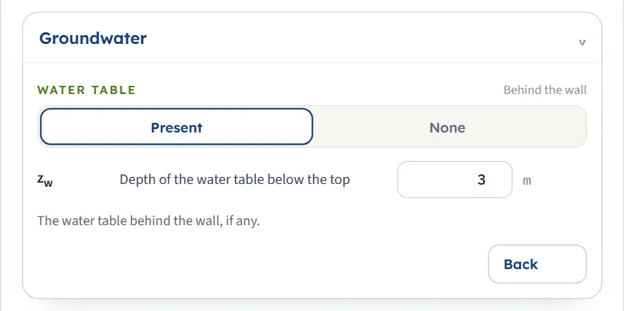
Water table has the buttons Present and None. With Present the box for the depth zw appears, and the saturated unit weight is asked for in each layer. With None the water table and the saturated unit weights are left out, the unit weight above the water table is used everywhere and the force from the water is zero.
| Field | Unit | Default | What to enter |
|---|---|---|---|
| Depth of the water table below the top zw | m · ft | 3 | Measured down from the top of the wall, behind the wall. Zero or more. A depth at or below the base of the wall has no effect. Shown when the water table is present. |
Choosing the state, the tension zone and the strength
Three decisions shape the answer. The state is a decision about the wall; the other two are about the soil.
| Choice | Options | What it does |
|---|---|---|
| State | Active, Passive | Active uses Ka and subtracts the cohesion term: the wall moves away from the soil. Passive uses Kp and adds it: the wall is pushed into the soil. The example gives 117.2 kN/m active and 927.5 kN/m passive. |
| Tension zone (active only) | Tension cracks — σ′ₐ = 0 above z₀, No cracks — theoretical Rankine | Matters when σ′a is negative near the top of a cohesive backfill. See below. |
| Strength (of each layer) | Drained — c′, φ′, Undrained — cᵤ, φᵤ = 0 | Drained uses the effective-stress parameters c′ and φ′. Undrained is a clay in the short term: cu with φu = 0, Ka = Kp = 1. |
Tension cracks or theoretical Rankine
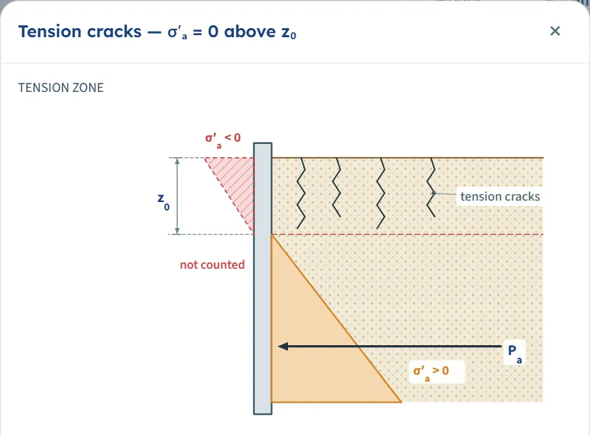
In a cohesive backfill the active pressure Ka σ′v − 2c′√Ka is negative near the top, down to the depth z0 where it is zero. Tension cracks — σ′ₐ = 0 above z₀, the default, takes the soil as unable to pull on the wall: cracks open down to z0, the soil loses contact with the wall there, and the negative part of the diagram is left out. No cracks — theoretical Rankine counts the negative area, which subtracts from the force and, being high on the wall, lowers the line of action. The (?) beside each button opens a window with a sketch and with the force for your current inputs.
With a wall of 6 m, the example layers and c′ = 10 kPa in layer 1, the module gives z0 = 2.165 m and, with cracks, Pa = 95.01 kN/m at 1.250 m above the base; without cracks, Pa = 82.51 kN/m at 0.6397 m. The Calculations tab states the force of the other assumption as well.
Undrained layers
Choose Undrained — cᵤ, φᵤ = 0 for a layer when you work in total stress, for a clay in the short term. The layer takes Ka = Kp = 1, so its pressure is the total vertical stress less 2cu (active) or plus 2cu (passive), with the water pressure inside it. With layer 1 of the example undrained at cu = 25 kPa, the module gives Pa = 93.15 kN/m at 1.209 m above the base and a tension zone down to z0 = 3.000 m, the base of that layer.
Which should I pick?
- State follows the wall. Use active for a wall that can move away from the soil, passive for the soil in front of a wall that is pushed into it. A wall that cannot move keeps the soil at rest: use At rest.
- Cracks are the usual design assumption for the active pressure on a wall the soil cannot pull; leave the default unless you want the theoretical figure to compare.
- Run both tension options on a cohesive backfill to see what the choice changes; the cracks option gives the larger force.
- Drained or undrained by the time scale. Drained parameters are for the long term, undrained for a clay in the short term.
Analyze and read the results
Press Analyze. The bar changes to Analysed — the earth pressure calculated and says “The inputs are locked. Edit inputs clears the results; the unit system can still be changed.” Press Analyze, then open the Results tab for a block of cards. The Section view now shows the coefficient of each layer; the pressures are in the Pressure view.
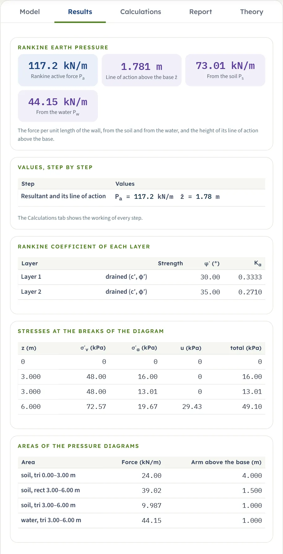
| Card | Symbol | What it is | The example |
|---|---|---|---|
| Rankine active force (passive when that state is chosen) | Pa or Pp | The resultant per unit length of wall, soil and water together. | 117.2 kN/m |
| Line of action above the base | z̄ | The height above the base at which the resultant acts. A dash when the net force is not a push. | 1.781 m |
| From the soil | Ps | The area of the soil pressure diagram. | 73.01 kN/m |
| From the water | Pw | The area of the water pressure diagram. Zero without a water table. | 44.15 kN/m |
| Depth of the tension zone | z0 | Shown only when the active pressure is negative at the top. | not shown |
Below the cards four tables give the working in numbers: Values, step by step; Rankine coefficient of each layer (strength, φ′, c′ and 2c′√Ka when a layer has cohesion, and Ka or Kp); Stresses at the breaks of the diagram (z, σ′v, σ′a, u and the total at each break); and Areas of the pressure diagrams (each triangle or rectangle with its force and its arm above the base).
Using the numbers
- The force is per unit length of wall, in kN/m (tf/m or kip/ft in the other unit systems); z̄ is a height above the base.
- The soil and the water are shown apart so that you can use the water part with your own water level or drainage assumption.
- Values are rounded where they are drawn, so the last digit of a figure on the drawing can differ by one from the card.
- Changing the unit system after Analyze re-states the cards and the report without a new run; the drawings keep their labels in m, kN/m³, kPa and kN/m. Edit inputs unlocks the model and clears the results.
Warnings and notes
The green bar carries a Warnings (0) button. It opens a window that says “No warnings — the assumptions of the solution hold for these inputs.” When a condition needs your attention the button counts it, and a note about the tension zone reads Notes (1); see Messages.
The Calculations tab, the report and the Theory tab
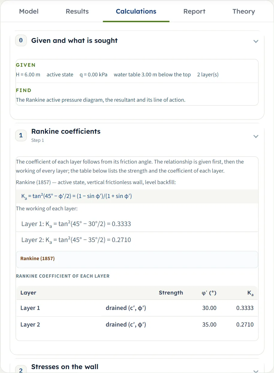
The Calculations tab opens with Given and what is sought and then writes out the working in numbered steps, ending with the answer:
- Rankine coefficients — the relationship (Ka = tan²(45° − φ′/2), or Kp for passive), the working of every layer with your friction angle, and a table of the strength and the coefficient of each layer (with the term 2c′√Ka when a layer has cohesion).
- Stresses on the wall — σ′a = Ka σ′v − 2c′√Ka (or the passive form), σ′v = q + Σγi Hi and u = γw (z − zw), then the tables of the stresses at the breaks of the diagram and of the areas of the pressure diagrams.
- Tension zone — only when the active pressure is negative at the top: z0, the assumption chosen, and the force that the other assumption would give.
- Resultant and its line of action — Pa = Σ areas and z̄ = Σ(area × arm) / Pa, with the soil and the water added.
The report
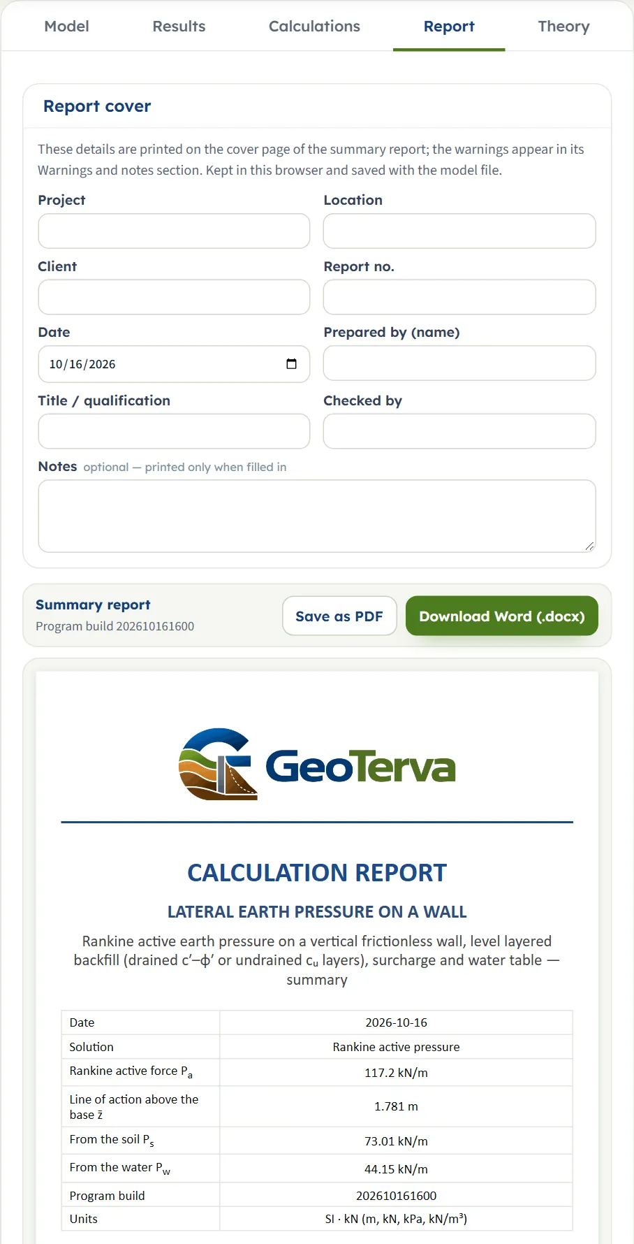
In the Report tab fill in the cover (project, location, client, report number, date, prepared by, title or qualification, checked by, and optional notes). The details are kept in this browser and saved with the model file. Save as PDF and Download Word (.docx) produce the summary report; the preview below the buttons is the report itself.
The report has six parts: 1 Introduction and scope, 2 Input data, 3 Calculation (3.1 Rankine coefficients, 3.2 Stresses on the wall, then 3.3 Resultant and its line of action; a Tension zone part is added when there is one), 4 Results, 5 Summary and 6 References. It carries the section, the pressure and the 3D drawings and states the units and the unit weight of water used.
The Theory tab
The Theory tab has five sections: Active and passive states, Cohesionless backfill, Cohesive backfill, Worked examples and References. Each opens when you click its title, and the figures in it are computed from the equations.
Worked example: the module’s own example
The module opens on this example, so you can follow the numbers on your own screen.
| Section | Input | Value |
|---|---|---|
| Wall | State, tension zone, height, surcharge | Active, cracks; H = 6 m; q = 0 |
| Soil layers | Layer 1 | 3 m; γ = γsat = 16 kN/m³; φ′ = 30°; c′ = 0 |
| Soil layers | Layer 2 | to the base; γ = γsat = 18 kN/m³; φ′ = 35°; c′ = 0 |
| Groundwater | Water table | Present; zw = 3 m |
Step 1: the coefficients
Ka = tan²(45° − 30°/2) = 1/3 = 0.3333 for layer 1 and tan²(45° − 35°/2) = 0.2710 for layer 2.
Step 2: the stresses
Layer 1 has no water in it: σ′v = 16 × 3 = 48.00 kPa at 3 m, and σ′a = 0.3333 × 48.00 = 16.00 kPa. At the top of layer 2, σ′a = 0.2710 × 48.00 = 13.01 kPa. Below the water table the effective unit weight is 18 − 9.81 = 8.19 kN/m³, so at 6 m σ′v = 48.00 + 8.19 × 3 = 72.57 kPa and σ′a = 0.2710 × 72.57 = 19.67 kPa. The water pressure at 6 m is u = 9.81 × 3 = 29.43 kPa.
Step 3: the areas and the resultant
The diagrams give four areas: soil, triangle 0–3 m, ½ × 16.00 × 3 = 24.00 kN/m at 4.000 m above the base; soil, rectangle 3–6 m, 13.01 × 3 = 39.02 kN/m at 1.500 m; soil, triangle 3–6 m, ½ × (19.67 − 13.01) × 3 = 9.987 kN/m at 1.000 m; water, triangle 3–6 m, ½ × 29.43 × 3 = 44.15 kN/m at 1.000 m.
These are the four cards of the Results tab, and the steps of the Calculations tab.
The same wall, passive
Choose Passive and press Analyze again (after Edit inputs). The coefficients are Kp = 3.000 and 3.690, the soil gives Ps = 883.4 kN/m, the water the same 44.15 kN/m, and the total is Pp = 927.5 kN/m at 1.985 m above the base.
A single layer of sand
For one layer of 16 kN/m³ sand at φ′ = 36° and no water, 6 m high, the formula P = ½ K γ H² applies. Active, Ka = 0.2596, so Pa = ½ × 0.2596 × 16 × 36 = 74.77 kN/m; the module gives 74.77 kN/m at 2.000 m, which is H/3. Passive, Kp = 3.852, so Pp = 1109 kN/m; the module gives 1,109 kN/m at 2.000 m.
Other unit systems
The default example in SI · tf gives Pa = 11.95 tf/m at 1.781 m, and in US 8.028 kip/ft at 5.844 ft: the same wall and soil in other units (117.15 kN/m is 11.95 tf/m and 8.028 kip/ft). Two checks by hand:
- US. A single layer of 120 pcf soil at 30°, H = 20 ft, no water and no surcharge: Ka = 1/3, so Pa = ½ × 0.3333 × 0.120 × 20² = 8.000 kip/ft acting at 20/3 = 6.667 ft. The module gives 8.000 kip/ft at 6.667 ft.
- SI · tf. A single layer of 1.6 t/m³ soil at 30°, H = 6 m, q = 1 t/m², no water: Pa = ½ × 0.3333 × 1.6 × 36 + 0.3333 × 1 × 6 = 9.60 + 2.00 = 11.60 tf/m, at (9.60 × 2 + 2.00 × 3) / 11.60 = 2.172 m. The module gives 11.60 tf/m at 2.172 m.
How each input changes the answer
Each row changes one thing in the example (active, tension cracks, H = 6 m, q = 0, layers of 16 kN/m³ at 30° and 18 kN/m³ at 35°, water table at 3 m) and runs the module again. The numbers are the ones the module gives, so you can reproduce any row. Forces are Pa, or Pp in the passive rows, in kN/m.
| Change | Force | z̄ (m) |
|---|---|---|
| The default example: active, cracks, water at 3 m The reference Soil 73.01 · water 44.15 kN/m | 117.2 | 1.781 |
| Passive Kp replaces Ka; the soil force is about twelve times larger, the water force is the same Soil 883.4 · water 44.15 kN/m | 927.5 | 1.985 |
| q = 20 kPa The soil force rises; the water force does not Soil 109.3 · water 44.15 kN/m | 153.4 | 2.106 |
| H = 8 m Layer 2 grows to 5 m; the force rises faster than the height, and the water force more than doubles Soil 116.8 · water 122.6 kN/m | 239.4 | 2.327 |
| H = 4 m The water table now cuts only 1 m of layer 2 Soil 38.12 · water 4.905 kN/m | 43.02 | 1.313 |
| φ′ of layer 1 = 25° A smaller friction angle gives a larger Ka and a larger soil force Soil 78.23 · water 44.15 kN/m | 122.4 | 1.876 |
| φ′ of layer 1 = 35° A larger friction angle gives a smaller force Soil 68.52 · water 44.15 kN/m | 112.7 | 1.693 |
| φ′ of layer 2 = 40° A larger friction angle in layer 2 also lowers the force Soil 63.33 · water 44.15 kN/m | 107.5 | 1.816 |
| Water table: None The water force is zero and the full unit weight acts in layer 2: the total falls Soil 84.97 · water 0 kN/m | 84.97 | 2.077 |
| zw = 1.5 m A higher water table: the water force rises and the soil force falls, but the total rises Soil 57.37 · water 99.33 kN/m | 156.7 | 1.804 |
| zw = 6 m (the base) The same as no water table Soil 84.97 · water 0 kN/m | 84.97 | 2.077 |
| γ of layer 1 = 18 kN/m³ A heavier layer 1 raises σ′v and the soil force Soil 80.89 · water 44.15 kN/m | 125.0 | 1.823 |
| γsat of layer 2 = 20 kN/m³ A heavier saturated layer raises σ′v below the water table Soil 75.45 · water 44.15 kN/m | 119.6 | 1.765 |
| c′ of layer 1 = 10 kPa, tension cracks The tension zone z0 appears; the force falls and the line of action drops Soil 50.87 · water 44.15 kN/m | 95.01 | 1.250 |
| c′ of layer 1 = 10 kPa, no cracks The negative area is counted: a smaller force and a much lower line of action Soil 38.37 · water 44.15 kN/m | 82.51 | 0.6397 |
| c′ of layer 1 = 10 kPa, passive Cohesion adds in the passive state Soil 987.3 · water 44.15 kN/m | 1,031 | 2.238 |
| Layer 1 undrained, cu = 25 kPa Ka = 1 and the cohesion term 2cu acts; tension down to the base of layer 1 Soil 49.01 · water 44.15 kN/m | 93.15 | 1.209 |
| Layer 1 undrained, cu = 25 kPa, passive Passive adds the term Soil 889.4 · water 44.15 kN/m | 933.5 | 2.078 |
| c′ = 40 kPa in both layers, cracks The soil pushes nowhere: only the water acts, and a note says so Soil 0 · water 44.15 kN/m | 44.15 | 1.000 |
| c′ = 40 kPa in both layers, no cracks A negative net force: a warning, and no line of action Soil -190.5 · water 44.15 kN/m | -146.3 | — |
The pattern follows the formulas. The soil force follows K, the unit weights and the surcharge; a higher water table adds water force faster than it removes soil force; cohesion lowers the active force and raises the passive one; and the line of action depends on where the pressure sits on the wall, so a tension zone at the top moves it down.
Messages: when the module stops, and what it notes
The module checks the numbers it needs before it calculates. When one cannot be used it stops, and nothing is calculated.
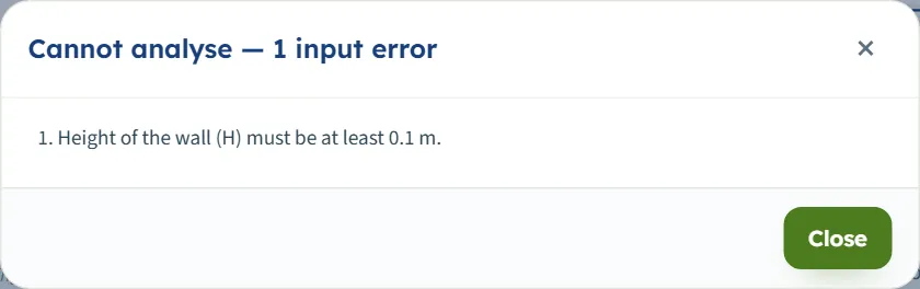
- If you press Analyze, a window titled Cannot analyse — 1 input error (or 2 input errors …) lists each message, and the box of the value is marked in red in the Model tab.
- A condition of the solution that is not met stops it in a window titled Cannot analyse — a condition of the solution is not met, which ends “Nothing was calculated. Change the inputs marked in red, then press Analyze again.”
- The limits are shown in the units of the unit system chosen.
| Kind | When | Message and what to do |
|---|---|---|
| Stop | The wall height is below 0.1 m or empty | “Height of the wall (H) must be at least 0.1 m.” or “… is missing.” Enter a height. |
| Stop | The surcharge is negative | “Uniform surcharge on the backfill (q) must be at least 0 kPa.” Enter zero or a positive load. |
| Stop | A thickness is below 0.01 m | “Thickness (H1) must be at least 0.01 m.” Enter a thickness. |
| Stop | A unit weight is below 1 | “Unit weight above the water table (γ1) must be at least 1 kN/m³.” Enter the unit weight of the soil. |
| Stop | The friction angle is outside 0° to 50° | “Effective friction angle (φ′1) must be at most 50°.” or “… at least 0°.” Enter an angle in that range. |
| Stop | A cohesion is negative | “Effective cohesion (c′1) must be at least 0 kPa.” Enter zero or more. |
| Stop | An undrained layer has no strength | “Undrained shear strength (cu,1) is missing.” Enter cu. |
| Stop | The water depth is negative | “Depth of the water table below the top (zw) must be at least 0 m.” Enter zero or more. |
| Stop | The layers above the last reach the base | “The layers above the last one already reach the base. The last layer would have no thickness. Reduce the layer thicknesses or the number of layers.” |
| Stop | A layer below the water table has γsat at or below 9.81 kN/m³ | “Layer 2: the saturated unit weight 9.00 kN/m³ is not above that of water. Below the water table the effective unit weight (saturated minus that of water) would be zero or negative, so σ′ᵥ would not grow with depth. Enter the saturated unit weight of the soil (above 9.81 kN/m³).” |
When more than one value is wrong the window lists them together, for example “2 input errors” with the wall height and the friction angle. In the table the layer number is part of the symbol: H1, φ′1, c′1 and γ1 belong to layer 1.
Notes and warnings
- A note. When the active pressure is negative over the whole height of the wall and cracks are assumed, the soil pushes nowhere and only the water acts. The Warnings button then reads Notes (1) and the window Notes and assumptions (1) says “σ′a is negative over the whole height of the wall.” The card Depth of the tension zone shows the height of the wall.
- A warning. With No cracks — theoretical Rankine, the same backfill gives a negative net force. The button reads Warnings (1) and a window opens: “The net active force is not a push: Pₐ = -146.35 kN/m. Counted over the whole height, the tension 2c′√Kₐ outweighs the pressure of the soil, so the soil would have to pull on the wall; the line of action is not given. Tension cracks (the other choice for the tension zone) give the pressure on a wall the soil cannot pull.” The line of action shows a dash.
Both come from c′ = 40 kPa in both layers of the example. With the usual values the window reads “No warnings — the assumptions of the solution hold for these inputs.”
Good practice and common mistakes
- Choose the state by what the wall does. Active needs the wall to move away from the soil; if it cannot move, the soil is at rest and At rest gives the pressure. Passive needs a movement into the soil, usually far larger than the active one.
- The last layer runs on to the base. Its thickness is not asked for; the layers above it must add up to less than H.
- Enter the saturated unit weight above 9.81 kN/m³ for any layer that reaches below the water table.
- Use the strength that fits the time scale. Drained c′ and φ′ for the long term; undrained cu with φu = 0 for a clay in the short term. Do not enter cu as c′.
- Take cohesion with care. In the active state it lowers the pressure; the cracks option leaves out the tension zone, and the theoretical option counts it. Compare both before you rely on a cohesive backfill.
- Read the soil and the water separately. Ps and Pw are on the cards, so you can use your own water level or drainage assumption.
- The force is per unit length of wall, in kN/m; z̄ is a height above the base.
- This module takes one uniform surcharge, a level backfill and a frictionless wall face. For a sloping backfill use Rankine, sloping backfill; for wall friction and a battered wall use Coulomb.
- Check the units after switching the system: type values in the units shown beside the boxes.
- Keep a record. The report is the record of an analysis; use Quick Save… or Save to file… to keep the model.
Frequently asked questions
How is the Rankine earth pressure on a wall calculated?
At each depth the pressure is σ′a = Ka σ′v − 2c′√Ka in the active state and σ′p = Kp σ′v + 2c′√Kp in the passive state, with Ka = tan²(45° − φ′/2) and Kp = tan²(45° + φ′/2), σ′v the vertical effective stress including the surcharge, and the water pressure u added below the water table. The force is the area of the diagrams, and the line of action is their centroid above the base. For the module’s example, Pa = 117.2 kN/m at 1.781 m above the base.
When do I use active and when passive?
Use active when the wall moves away from the soil enough for the soil behind it to reach its limit state, and passive for the soil in front of a wall that is pushed into it. For the module’s example the same wall gives 117.2 kN/m active and 927.5 kN/m passive.
What are the tension cracks, and which option should I use?
In a cohesive backfill the active pressure is negative near the top, down to the depth z0. With Tension cracks the soil is taken as unable to pull on the wall, and the negative part is left out. With No cracks — theoretical Rankine it is counted. Cracks is the default and the usual design assumption; the Calculations tab states the force of the other option.
How do I model a clay in the short term?
Choose Undrained — cᵤ, φᵤ = 0 for the layer and enter the undrained shear strength cu. The layer takes Ka = Kp = 1, and its pressure is the total vertical stress less (active) or plus (passive) 2cu, with the water pressure inside it.
How many layers can I enter, and how does the last one work?
Up to six, from the top down. The last layer has no thickness: it runs on to the base of the wall, and the layers above it must add up to less than the wall height.
How do I handle the water table?
In Groundwater choose Present and enter the depth zw below the top of the wall; enter the saturated unit weight of each layer, which must be above 9.81 kN/m³. Below the water table the effective unit weight γsat − γw is used and the water pressure is added. Choose None to leave the water out; a depth at the base of the wall gives the same result.
Does the module include a surcharge?
Yes, one uniform surcharge q over the whole backfill surface; it adds to the vertical stress at every depth. For a point, line, strip, triangular, ramp or area load, use the Surcharge loads manuals and add the pressure to this one.
What values does the module accept?
The wall height at least 0.1 m, the surcharge zero or more, each thickness at least 0.01 m, each unit weight at least 1 kN/m³, the friction angle from 0° to 50°, the cohesion zero or more, and the water depth zero or more. Anything else stops the analysis with a message that names the value.
Can I drag the layers or the water table on the drawing?
No. The drawing has no drag handles; change the values in the Model tab and the drawing follows. After Analyze the inputs are locked until you press Edit inputs.
Which units does it use, and what are the units of the answer?
SI · kN, SI · tf or US, switchable in the header at any time, even after Analyze. The force is in kN/m, tf/m or kip/ft, pressures in kPa, t/m² or ksf, and lengths in m or ft. The default example gives 117.2 kN/m, 11.95 tf/m or 8.028 kip/ft.
What does the report contain?
A cover with your project details and the answer, then six parts: introduction and scope, input data, the calculation step by step, results, summary and references, with the section, pressure and 3D drawings. It is saved as a PDF or a Word file once the model is analysed.
Does the module remember my inputs?
Yes. Every change is kept in the browser, and the page opens again on the model you last worked on, including its analysed state. Reset to defaults brings back the example; Save to file and Quick Save keep copies.