

What the module calculates
Uniform load gives the extra lateral pressure that a load spread over the whole ground surface behind a wall pushes on the wall. The load raises the vertical stress by q at every depth, and the wall feels the fraction K of it, so the added pressure is the same from the top of the wall to its base:
σH is the lateral pressure the surcharge adds, P is its resultant per unit length of wall, and zR is the depth below the ground at which P acts. K is the lateral earth-pressure coefficient: you choose it by how the wall behaves, as the at-rest coefficient, the active coefficient, or a value you enter.
What you can describe
- A wall of height H (greater than zero) with a uniform surcharge q of zero or more over the whole retained surface.
- The coefficient in one of three ways: At rest · rigid wall (K0 = 1 − sin φ′, Jaky), Active · yielding wall (Ka = tan²(45° − φ′/2), Rankine) or Enter K, a value from 0 to 3 that you supply.
The module gives the coefficient, the pressure, the resultant and its depth, draws the load and the pressure diagram in elevation, in plan and in 3D, writes out the working, and prepares a PDF or Word report.
What belongs to other modules
- This is the surcharge component only. It is added to the earth-pressure and water-pressure diagrams of the wall calculation, where you combine the three.
- A load that stops short of the wall or has a limited width is not uniform in this sense. Those cases have their own modules: Point load (a concentrated load behind the wall), Strip load (a uniform load on a strip parallel to the wall), Line load (a line load parallel to the wall), Triangular load (a load that rises linearly across a strip), Area loads (rectangular loaded areas in plan) and Ramp load (a load rising from zero to a plateau).
Before you start: what you need
Have these ready from your design:
| What | Where it comes from | Notes |
|---|---|---|
| The wall height H | Your design | The height over which the pressure acts, from the ground surface to the base of the wall. It must be greater than zero. |
| The surcharge q | Your design loading | A load per unit area on the ground behind the wall, spread over the whole retained surface. Zero or more. |
| How the wall behaves | Your design | A wall that is propped, anchored or otherwise cannot move keeps the soil at rest. A wall that yields enough lets the soil reach its active state. This decides the coefficient. |
| The friction angle φ′ of the retained soil | Tests or correlations | An effective friction angle, from 0° to below 90°. Needed for the at-rest and active options. |
| Or the coefficient K itself | Another source | For a case the two formulas do not cover: an overconsolidated K0, a Coulomb Ka for a rough or inclined wall, or a value measured or back-analysed on site. From 0 to 3. |
Quick start in seven steps
- Open the module and choose the units
Open Uniform load from the Surcharge Loads family. Pick SI · kN, SI · tf or US in the header; you can change it at any time.
- Enter the wall height
In Geometry, type the wall height H.
- Enter the surcharge
In Uniform load, type the surcharge q. It acts over the whole retained surface.
- Choose the coefficient
In Lateral pressure coefficient, pick At rest · rigid wall, Active · yielding wall or Enter K. The first two ask for the friction angle φ′; the third asks for K. The (?) beside each option opens a window with a sketch of what it assumes.
- Press Analyze
Press Analyze at the foot of the Model tab. The bar reads Analysed, the inputs lock, and the pressure and the resultant appear on the drawing.
- Read the answer
The Results tab gives K, the lateral pressure σH, the resultant force P and the resultant depth zR. The Elevation, Plan and 3D View buttons change the view.
- Take the working and the report
The Calculations tab shows the three steps with your numbers. The Report tab saves a PDF or a Word file.
The screen: three views of the wall
The layout is the one every GeoTerva module shares, described in the workspace guide. For this module the drawing has three views, chosen with the buttons above it:
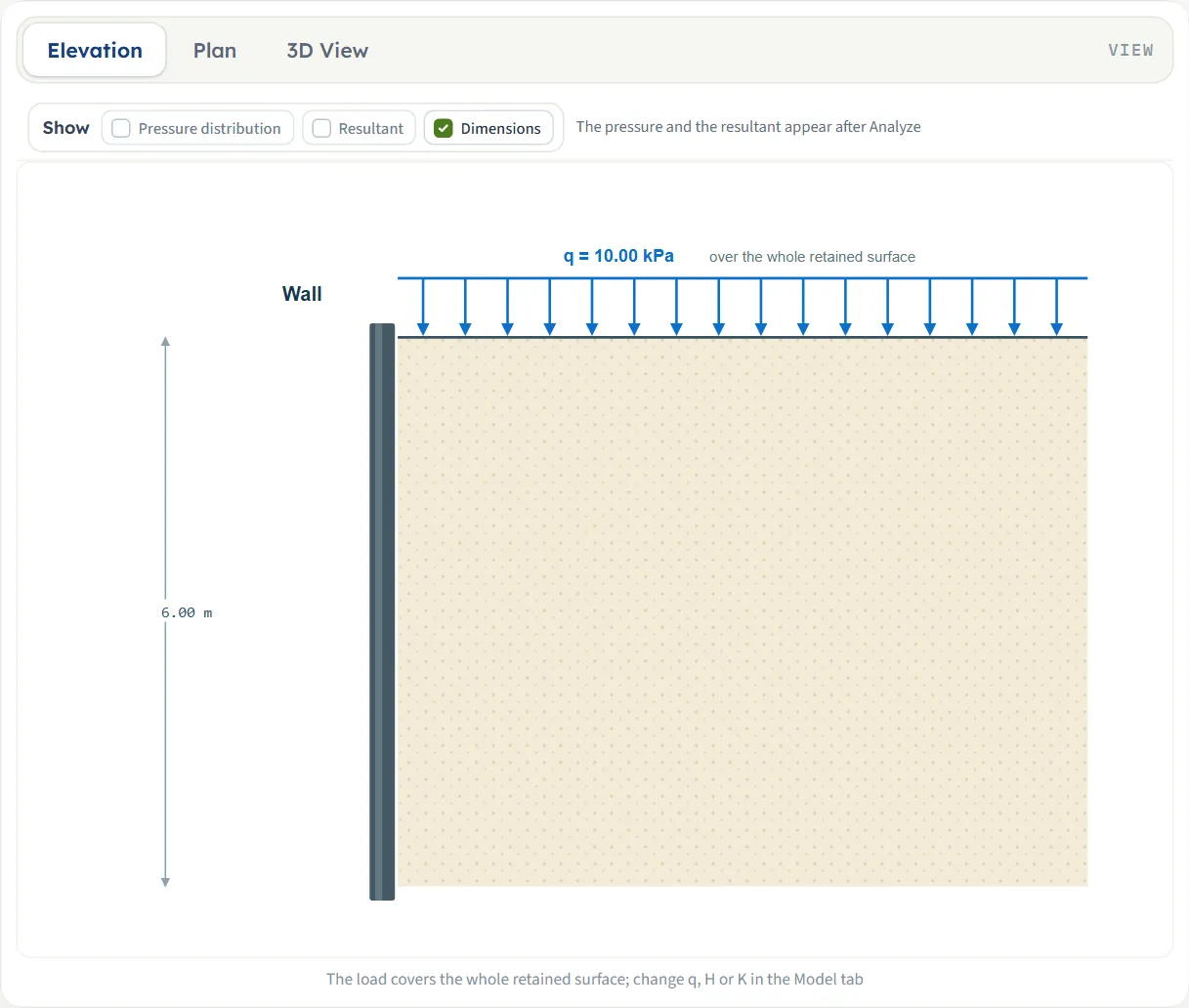
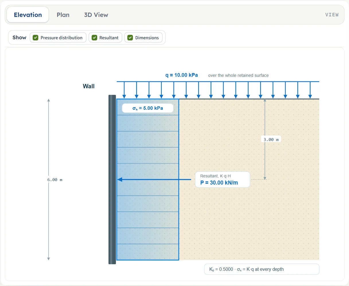
- Elevation is a section through the wall and the retained ground: the wall, the soil, the load as a row of arrows with its value, and the wall height H. After Analyze it adds the pressure diagram on the wall (a rectangle, with its value σH and the coefficient), the resultant P acting on the wall at mid-height, and the depth zR.
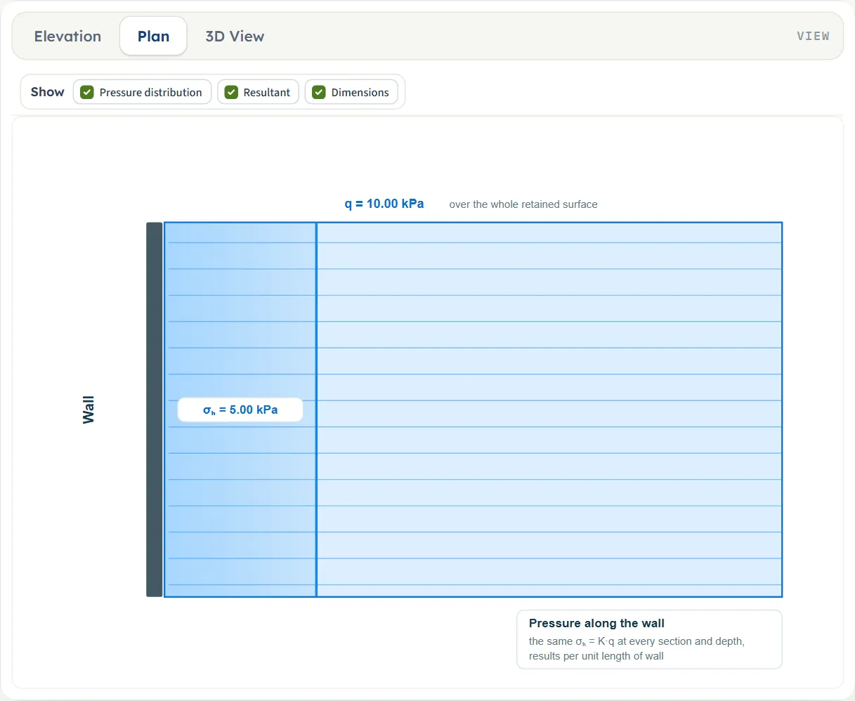
- Plan looks down on the retained ground. The load covers all of it; after Analyze the strip of pressure along the wall is drawn, with a note that the pressure is the same at every section and depth and that results are per unit length of wall.
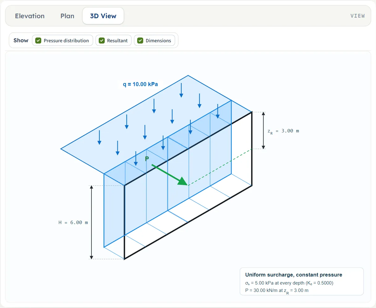
- 3D View shows the wall, the loaded ground behind it and, after Analyze, the pressure as a curtain on the wall face, the resultant P and the dimensions H and zR.
The Show chips
Above the drawing a Show bar has three chips. Pressure distribution and Resultant are available after Analyze, and until then the bar says “The pressure and the resultant appear after Analyze”. Dimensions can be switched at any time: it shows or hides the dimension lines with their values: H, and zR when the resultant is shown, in the elevation and the 3D view. The Resultant chip acts on the elevation and the 3D view; a plan has no place for a resultant.


Entering the model, section by section
The Model tab has three sections. Each opens when you click its title; Next and Back at the foot walk you through them, and Analyze waits below the last one. The tables list every field with its symbol, the unit in each unit system and its default. Where a unit is shown twice or three times, such as m · ft, the units are those of SI · kN, SI · tf and US in turn, and equal ones are merged. Defaults are shown in SI; in SI · tf the surcharge box shows 1.02 t/m², and in US the boxes show 19.69 ft and 0.2089 ksf for the same wall and load.
Geometry
One number: the height of the wall.
| Field | Symbol | Unit | Default | What to enter |
|---|---|---|---|---|
| Wall height | H | m · ft | 6.00 | The height of the wall over which the surcharge pressure acts, from the ground surface to the base. It must be greater than zero; a blank or zero box stops the analysis. |
Uniform load
One number: the surcharge. The load acts over the whole retained surface, from the wall to the far edge of the drawing, so no distance from the wall is asked for.
| Field | Symbol | Unit | Default | What to enter |
|---|---|---|---|---|
| Uniform surcharge | q | kPa · t/m² · ksf | 10.00 | The load on the ground behind the wall, as a pressure, spread over the whole retained surface. Zero or more; zero gives zero pressure. |
Lateral pressure coefficient
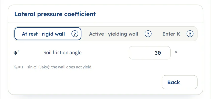
Three buttons choose how K is found; each has a (?) that opens a help window. The box under them follows the choice: the friction angle φ′ for the first two options, the coefficient K for Enter K. A line under the boxes states the formula of the option chosen or, for Enter K, where such a coefficient can come from.
| Field | Symbol | Unit | Default | What to enter |
|---|---|---|---|---|
| Soil friction angle | φ′ | ° | 30 | Effective friction angle of the retained soil, from 0° to below 90°. It gives K0 or Ka, depending on the option. Shown when At rest · rigid wall or Active · yielding wall is chosen. |
| Lateral pressure coefficient | K | — | 0.5 | The coefficient you supply, from 0 to 3. The friction angle is not used. Shown when Enter K is chosen. |
Choosing the lateral pressure coefficient
The pressure is the load times a coefficient, so the choice of K is the one decision in this module. The three options:
| Option | Coefficient | Use it when | What the module says |
|---|---|---|---|
| At rest · rigid wall (the default) | K0 = 1 − sin φ′, Jaky, normally consolidated soil | The wall is propped, anchored or otherwise cannot move. | The wall does not yield, so the soil keeps its at-rest state. |
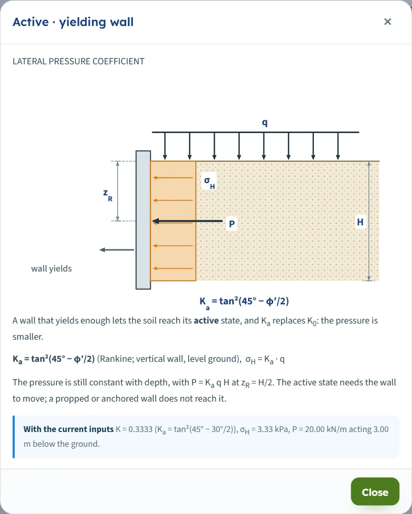
| Active · yielding wall | Ka = tan²(45° − φ′/2), Rankine, vertical wall and level ground | The wall yields enough for the soil to reach its active state. | The pressure is smaller than at rest. The active state needs the wall to move; a propped or anchored wall does not reach it. |
| Enter K | K from 0 to 3, as you enter it | The two formulas do not cover the case: an overconsolidated K0, a Coulomb Ka for a rough or inclined wall, or a value measured or back-analysed on site. | The friction angle is not used. |
How the two formulas compare
For the same friction angle the at-rest coefficient is the larger. The table gives K as the module returns it for each friction angle. Under the example surcharge of 10 kPa the pressure σH in kPa is ten times K.
| φ′ | At rest K0 | Active Ka |
|---|---|---|
| 20° | 0.6580 | 0.4903 |
| 25° | 0.5774 | 0.4059 |
| 30° | 0.5000 | 0.3333 |
| 35° | 0.4264 | 0.2710 |
| 40° | 0.3572 | 0.2174 |
At φ′ = 0° both options return K = 1.0000, so the surcharge acts on the wall at full value.
The (?) windows
The (?) beside each option opens a window with a sketch of the wall, the load and the pressure rectangle for that option, the formula, and a line headed With the current inputs that gives K, σH and P and the depth of P for your H, q and φ′. Reading a window changes nothing in the model.
Which should I pick?
- Start from how the wall is held. A wall that is propped, anchored or cast against something rigid does not move: leave the default, At rest · rigid wall.
- Choose Active only when the wall really yields enough for the soil to reach its active state. If you cannot tell, run both and compare: the at-rest value is the larger for the same friction angle.
- Use Enter K for a value from elsewhere: an overconsolidated K0, a Coulomb Ka for a rough or inclined wall, a measured value. The module accepts 0 to 3.
Analyze and read the results
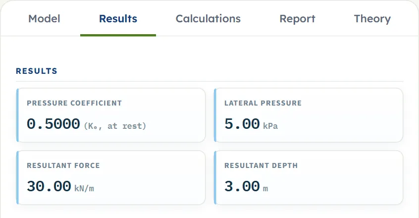
Press Analyze. The bar changes to Analysed — the lateral pressure calculated and says “The inputs are locked. Edit inputs clears the results; the unit system can still be changed.” The Results tab shows four cards, and the drawing now carries the pressure and the resultant.
| Card | Symbol | What it is | The example |
|---|---|---|---|
| Pressure coefficient | K | The coefficient used, with its kind in brackets: (K0, at rest), (Ka, active) or (entered). | 0.5000 |
| Lateral pressure | σH | The pressure the surcharge adds to the wall, the same at every depth. | 5.00 kPa |
| Resultant force | P | The resultant per unit length of wall, in kN/m (tf/m or kip/ft in the other systems). | 30.00 kN/m |
| Resultant depth | zR | The depth below the ground at which P acts, always H/2; it is also the height of P above the base. | 3.00 m |
Using the numbers
- The pressure diagram is a rectangle: σH over the full height H. In the wall calculation add it to the earth-pressure and water-pressure diagrams.
- P is a force per unit length of wall, and acts at zR = H/2 below the ground.
- Changing the unit system after Analyze re-states the cards, the drawing and the report without a new run. Edit inputs unlocks the model and clears the results.
The Calculations tab and the report
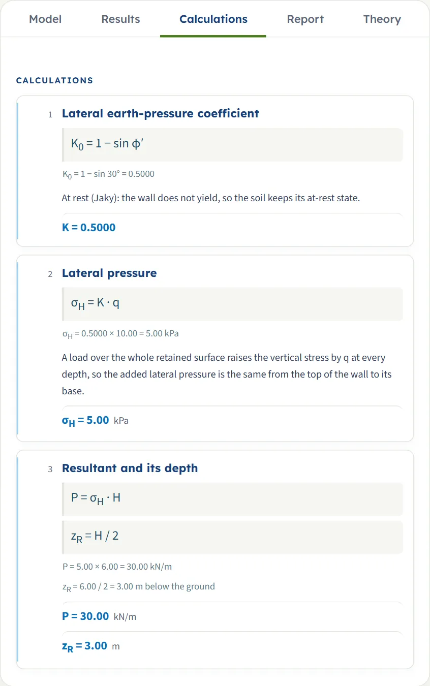
The Calculations tab writes out the working in three numbered steps. Each step shows its equation (or, for an entered K, the value), the equation with your numbers, and the result; the first two steps add a short note:
- Lateral earth-pressure coefficient — K0 = 1 − sin φ′, or Ka = tan²(45° − φ′/2), or the value entered, with the number it gives.
- Lateral pressure — σH = K · q, with the note that a load over the whole retained surface raises the vertical stress by q at every depth, so the added pressure is the same from the top of the wall to its base.
- Resultant and its depth — P = σH · H and zR = H / 2, with the results.
Before Analyze the tab says “Press Analyze on the Model tab to calculate the lateral pressure.”
The report
In the Report tab fill in the cover (project, location, client, report number, date, prepared by, title, checked by, and optional notes). The details are kept in this browser. After Analyze, Save as PDF and Download Word (.docx) are available; before it they are greyed out. The preview below the buttons is the report itself.
The report has six parts: 1 Introduction and scope, 2 Input data, 3 Calculation (one part for each of the three steps), 4 Results, 5 Summary and 6 References. It carries the elevation, the plan and the 3D drawing, and states the units with the conversion constants.

The Theory tab has five sections: Uniform load on a wall, Lateral pressure, Resultant and line of action, a worked example, and References.
Worked example: the module’s own example
The module opens on this example, so you can follow the numbers on your own screen.
| Section | Input | Value |
|---|---|---|
| Geometry | Wall height | H = 6 m |
| Uniform load | Surcharge | q = 10 kPa |
| Lateral pressure coefficient | Option, friction angle | At rest · rigid wall; φ′ = 30° |
Step 1: the coefficient
K0 = 1 − sin 30° = 1 − 0.5 = 0.5000.
Step 2: the lateral pressure
σH = K · q = 0.5000 × 10.00 = 5.00 kPa, at every depth from the top of the wall to its base.
Step 3: the resultant and its depth
These are the four numbers on the Results tab, and the three steps of the Calculations tab.
The same wall, active
Choose Active · yielding wall and press Analyze again (after Edit inputs). Ka = tan²(45° − 30°/2) = tan²(30°) = 0.3333, so σH = 3.33 kPa and P = 20.00 kN/m at 3.00 m: two thirds of the at-rest force.
The same kind of wall in US units
Switch to US and enter H = 20 ft and q = 0.25 ksf with the at-rest coefficient at 30°. The module gives K = 0.5000, σH = 0.1250 ksf, P = 2.50 kip/ft at zR = 10.00 ft, which is 0.5 × 0.25 = 0.125 ksf, 0.125 × 20 = 2.50 kip/ft and 20/2 = 10 ft by hand.
How each input changes the answer
Each row changes one thing in the example (H = 6 m, q = 10 kPa, φ′ = 30°, at rest) and runs the module again. The numbers are the ones the module gives, so you can reproduce any row.
| Change | K | σH (kPa) | P (kN/m) | zR (m) | What happens |
|---|---|---|---|---|---|
| The default example: at rest, φ′ = 30° | 0.5000 | 5.00 | 30.00 | 3.00 | The reference |
| Active wall | 0.3333 | 3.33 | 20.00 | 3.00 | Ka = tan²(30°) replaces K0; the pressure and the force are two thirds |
| K entered = 0.3 | 0.3000 | 3.00 | 18.00 | 3.00 | The friction angle is not used; σH = 0.3 × 10 |
| K entered = 3 | 3.0000 | 30.00 | 180.00 | 3.00 | The largest value the module accepts |
| φ′ = 25° (at rest) | 0.5774 | 5.77 | 34.64 | 3.00 | A smaller friction angle gives a larger K0 |
| φ′ = 35° (at rest) | 0.4264 | 4.26 | 25.59 | 3.00 | A larger friction angle gives a smaller K0 |
| φ′ = 40° (at rest) | 0.3572 | 3.57 | 21.43 | 3.00 | Smaller again |
| Active, φ′ = 35° | 0.2710 | 2.71 | 16.26 | 3.00 | The active coefficient is again the smaller of the two |
| φ′ = 0° (at rest) | 1.0000 | 10.00 | 60.00 | 3.00 | K = 1: the full surcharge acts on the wall |
| H = 4 m | 0.5000 | 5.00 | 20.00 | 2.00 | σH does not change; P and zR follow H |
| H = 8 m | 0.5000 | 5.00 | 40.00 | 4.00 | The same, upward |
| q = 20 kPa | 0.5000 | 10.00 | 60.00 | 3.00 | σH and P double |
| q = 0 | 0.5000 | 0.00 | 0.00 | 3.00 | No pressure; the resultant is zero |
The pattern follows the formulas: P = K q H is proportional to each of the three, and zR depends on the wall height alone.
Messages: when the module stops
The module checks the numbers it needs: the wall height, the surcharge, and the friction angle (or the entered K). When one of them cannot be used it stops, and nothing is calculated.
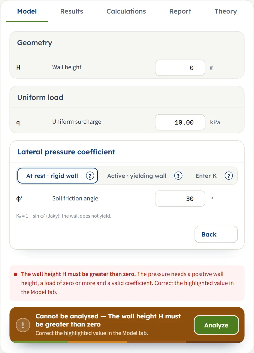
- A red message appears in the Model tab above the Analyze bar, and the bar turns brown and reads Cannot be analysed, followed by the message.
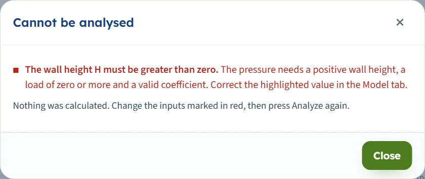
- If you press Analyze, a window titled Cannot be analysed gives the message and says “Nothing was calculated. Change the inputs marked in red, then press Analyze again.”
- The Results tab says “Not calculated — see the Model tab.”, and the drawings say “Not calculated — correct the highlighted input in the Model tab”.
| Kind | When | Message and what to do |
|---|---|---|
| Stop | The wall height is zero, negative or empty | “The wall height H must be greater than zero.” Enter a height above zero. |
| Stop | The surcharge is negative or empty | “The surcharge q must be zero or more.” Enter zero or a positive load. |
| Stop | At rest or Active is chosen and φ′ is outside 0° to below 90°, or empty | “Enter a friction angle φ′ from 0° to below 90°.” Enter an angle in that range, or choose Enter K. |
| Stop | Enter K is chosen and K is outside 0 to 3, or empty | “Enter a coefficient K between 0 and 3.” Enter a value in that range. |
Every message continues with the same two sentences: “The pressure needs a positive wall height, a load of zero or more and a valid coefficient. Correct the highlighted value in the Model tab.”
When more than one value is wrong, the messages are joined in one stop, for example “The wall height H must be greater than zero; The surcharge q must be zero or more.” With Enter K chosen the friction angle is not used, so its box is not checked.
Good practice and common mistakes
- Choose K by how the wall is held, not by habit. The default, at rest, is for a wall that does not move. Choose active only when the wall yields enough to reach that state; if you are not sure, run both and compare.
- Use this module only for a load over the whole retained surface. A load of limited width or length, or one that starts away from the wall, belongs to the Strip load, Area loads or Ramp load module, or to the point, line or triangular ones.
- Enter q as a pressure, load per unit area, not as a force per metre of wall. In US units q is in ksf: 10 kPa is 0.2089 ksf.
- Read P per unit length. It is in kN/m, so multiply by the length of wall only when you need a total force on a length of wall.
- Add the result to the other pressures. σH is the surcharge component only; the wall calculation combines it with the earth pressure of the soil and the water pressure.
- Use Enter K for a value from another source, from 0 to 3, such as an overconsolidated K0 or a Coulomb Ka. The friction angle is then not used.
- Note your values. The module opens on its example every time and does not keep what you typed; the report is the record of an analysis.
- Check the units after switching the system: type values in the units shown beside the boxes.
Frequently asked questions
How is the lateral pressure from a uniform surcharge calculated?
A load q over the whole retained surface raises the vertical stress by q at every depth, and the wall feels the fraction K of it: σH = K · q. The resultant is P = σH · H per unit length of wall, acting at zR = H/2 below the ground. For the module’s example, K0 = 0.5000, σH = 5.00 kPa and P = 30.00 kN/m at 3.00 m.
Why is the pressure the same at every depth?
Because the load covers the whole retained surface, it raises the vertical stress by the same q at every depth, and the coefficient K is a constant. The diagram is a rectangle from the top of the wall to its base, so the resultant is at mid-height.
Should I use the at-rest or the active coefficient?
Use at rest, K0 = 1 − sin φ′, for a wall that cannot move: propped, anchored or otherwise held. Use active, Ka = tan²(45° − φ′/2), only for a wall that yields enough for the soil to reach its active state. For φ′ = 30° the two coefficients are 0.5000 and 0.3333.
What if the load does not cover the whole surface?
Then it is not a uniform load in the sense of this module. A load on a strip parallel to the wall, a line load, a point load, a triangular load, a ramp load or rectangular loaded areas each have their own Surcharge Loads module, which gives the pressure at each depth and its resultant.
Does the result include the earth pressure of the soil and the water pressure?
No. The result is the surcharge component only. You add it to the earth-pressure and water-pressure diagrams in the wall calculation.
What values does the module accept?
The wall height must be greater than zero, the surcharge zero or more, the friction angle from 0° to below 90° (for the at-rest and active options) and an entered coefficient from 0 to 3. Anything else stops the analysis with a message that names the value.
Can I drag the load on the drawing?
No: a uniform load covers the whole retained surface, so it has no position. Change q, H or K in the Model tab; the drawing follows. After Analyze the inputs are locked until you press Edit inputs.
Which units does it use, and what are the units of the answer?
SI · kN, SI · tf or US, switchable in the header at any time, even after Analyze. The pressure is in kPa, t/m² or ksf, and the resultant per unit length in kN/m, tf/m or kip/ft; the depth is in m or ft.
Why does the resultant act at mid-height?
The pressure is constant over the height of the wall, so its resultant, σH H, acts at the middle of the rectangle: zR = H/2 below the ground, which is also H/2 above the base.
What does the report contain?
A cover with your project details and a summary, then six parts: introduction and scope, input data, the calculation step by step, results, summary and references, with the elevation, plan and 3D drawings. It is saved as a PDF or a Word file after Analyze.
Does the module remember my inputs?
No. It opens on its example (6 m wall, 10 kPa, 30°, at rest) each time the page is opened. The report cover details you type are kept in the browser, and the unit system is remembered.