

What the module calculates
Sheet pile in sand designs a cantilever or anchored sheet-pile wall driven into sand. It builds the net pressure diagram on the wall, finds the depth of embedment from the equilibrium of the diagram, gives the maximum bending moment and the section modulus it asks for, verifies the sheet pile you give to EN 1993-1-1 or AISC 360-22, and estimates the movement of the wall. With rows of ground anchors the wall is held at their levels and the module gives the anchor force of each row.
The soil is sand, entered in up to four layers from the top of the wall down the whole profile: the layers above the dredge line press on the wall as Rankine active pressure, and the layers below it act on both faces, active on the retained side and passive on the excavation side:
The net pressure below the dredge line starts at the active pressure there and falls to zero at the point E, a distance L3 below the dredge line. A cantilever wall is then balanced by an equation of the fourth degree in the depth of the toe below E (the toe-pressure reversal is idealised as the conventional limit-equilibrium method does), and the maximum moment lies where the shear is zero.
What you can describe
- A wall of height L above the dredge line, as a cantilever or with one to four rows of ground anchors.
- Up to four layers of sand, each with its own unit weights and friction angle.
- Water on the retained side, at the same level on the excavation side or at a different level (the net hydrostatic pressure is added; no seepage).
- A level or sloping retained surface, and up to six surcharges: uniform, strip and point loads.
- A pseudo-static earthquake check with Mononobe–Okabe pressures.
- The embedment calculated by the module, by a depth factor or by a factor of safety on Kp, or given by you and verified.
- The sheet pile by its grade, its section modulus and its second moment of area.
Which module for which wall
- Sand above and below the dredge line: this module. Undrained clay: Sheet pile in clay. A profile of sand and clay layers, with short- and long-term scenarios: Anchored sheet pile on layered soil.
- The Rankine coefficients on their own, or the pressure of a sloping backfill: Rankine, Rankine, sloping backfill; the active force in an earthquake: Mononobe–Okabe.
- The pressure of a strip or point load on a wall: Surcharge loads.
Before you start: what you need
Have these ready from your design and your ground investigation:
| What | Notes | |
|---|---|---|
| The wall height L Your design | From the top of the wall to the dredge line (the excavation level). At least 0.5 m. | |
| The sand layers Boring logs and tests | For each layer from the top down: thickness (not the last), moist and saturated unit weight, friction angle φ′ from 15° to 45°, and the horizontal subgrade reaction kh for the displacement. | |
| The water levels Groundwater readings | The depth Dw of the water table behind the wall and, if it differs, the level in the excavation; or no water. | |
| Surcharges, slope, anchors Your design loading | Uniform, strip and point loads; the slope angle β; for each anchor row its depth, spacing, inclination, lock-off load and lengths. | |
| The design route Your design basis | A depth factor f (1.2 to 1.3 is usual) or a factor of safety FSp on Kp. | |
| The sheet pile | The maker’s table | The steel grade, the section modulus per metre of wall and its second moment of area; the code and its factors. |
Quick start in eight steps
- Open the module and choose the units
Open Sheet pile in sand from the Sheet-Pile Walls family. Pick SI · kN, SI · tf or US in the header; you can change it at any time, even after Analyze.
- Enter the sand
In Soil layers fill the New layer form and press + Add layer, or change the first layer, Sand-1, by pressing its row. The last layer runs on below the toe.
- Set the water, the wall and the embedment
In Groundwater choose the levels. In Wall and embedment type L and leave the depth Calculated by the program (or give it).
- Add what acts on the wall
Choose Sloping in Terrain, add rows of anchors in Ground anchor, loads in Surcharge and switch on the Earthquake check, as your design needs. A wall without anchors is a cantilever.
- Choose the safety route and the sheet pile
In Design factors choose the depth factor or the factor of safety on Kp. In Sheet pile and Design code give the grade, the section modulus and the code.
- Press Analyze
Press Analyze at the foot of the Model tab. The bar reads Analysed — the sheet-pile wall calculated and the inputs lock. If something needs your attention a window with the warnings opens by itself.
- Read the answer
The Results tab gives the diagrams, the embedment, the moment, the section modulus asked for, the verdict on the sheet pile given and the displacement; with anchors, the anchor force of each row.
- Take the working and the report
The Calculations tab writes out every step with your numbers. The Report tab saves a PDF or a Word file.
The screen: section, 3D and the handles
The layout is the one every GeoTerva module shares, described in the workspace guide: the drawing on the left, the tabs Model, Results, Calculations, Report and Theory on the right. The drawing has two views, chosen with the buttons above it:
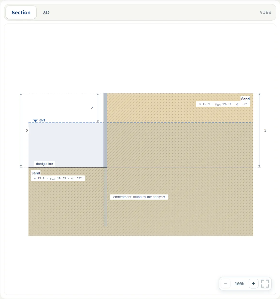
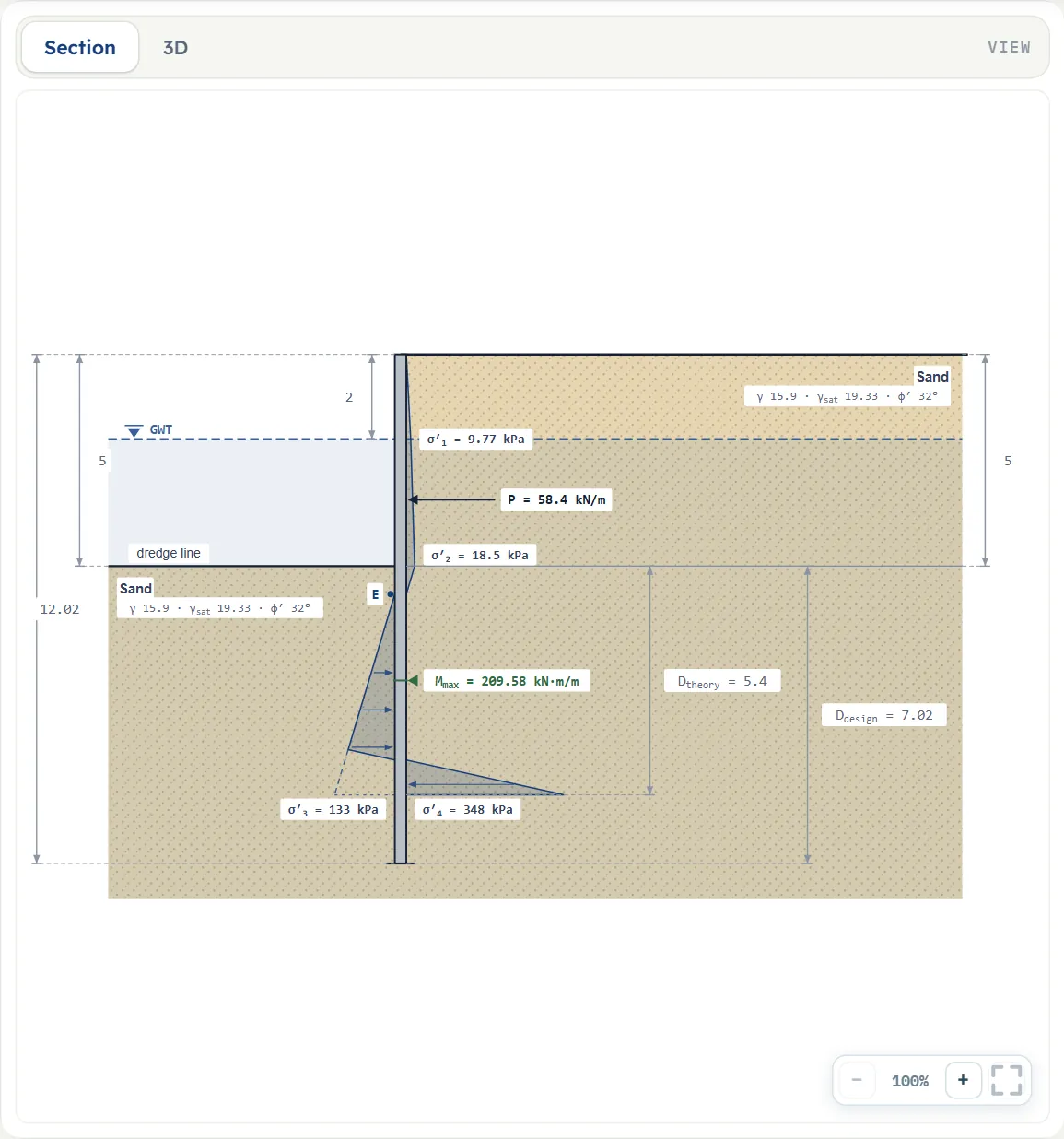
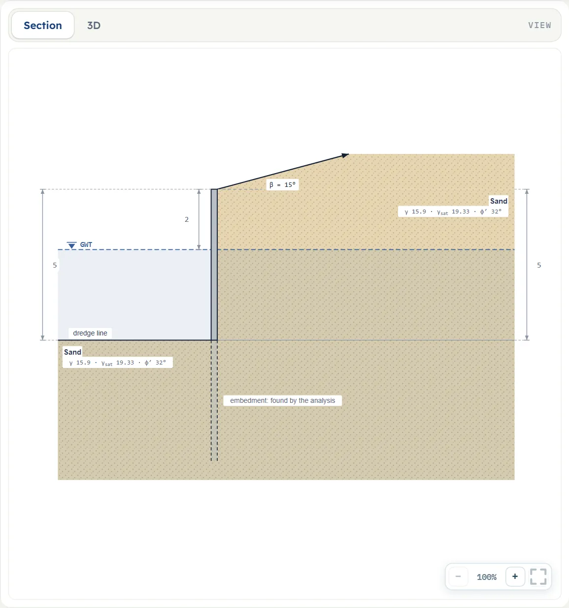
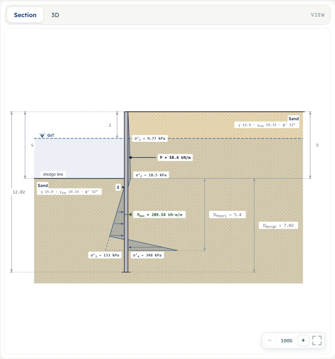
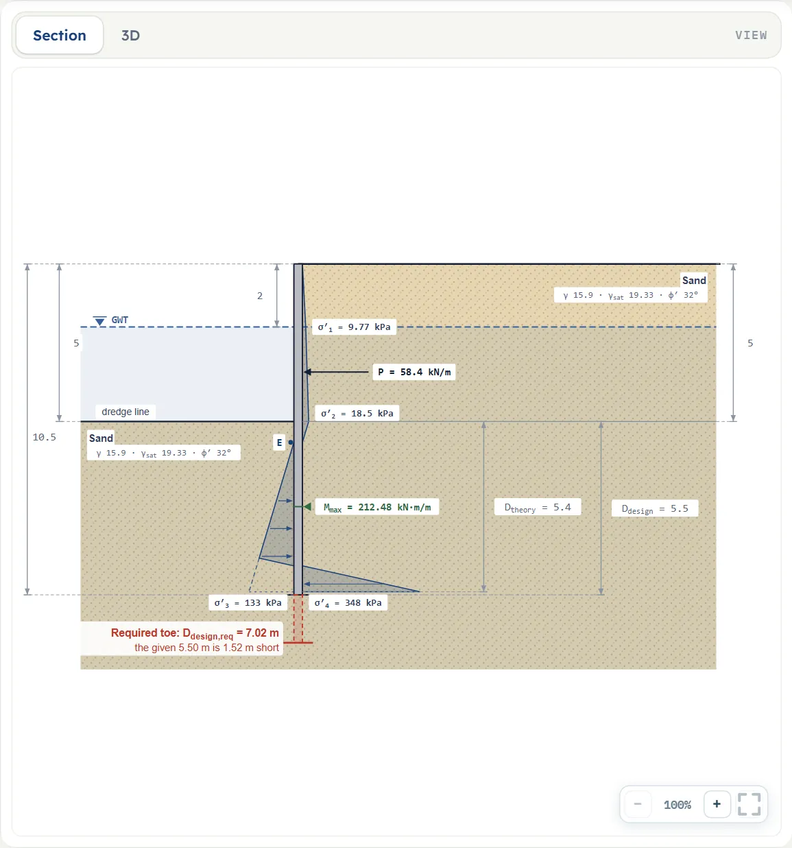
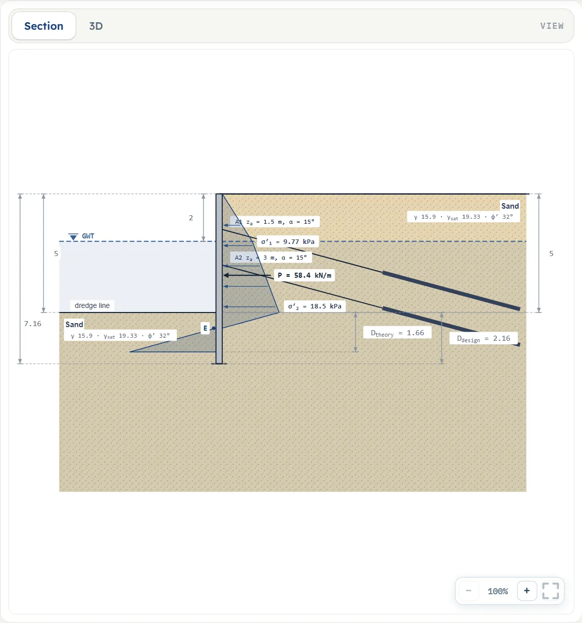
- Section is the wall with the retained layers, the water levels, the dredge line, the anchors and the loads. It follows your inputs. Before Analyze it shows the wall, the layers, the water levels, the loads and the dredge line, with a dashed toe marked “embedment: found by the analysis”; after it, the net pressure diagram, Dtheory, Ddesign, the total length and Mmax, which is green where the sheet pile given carries it and red where it does not.
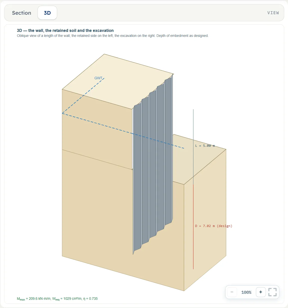
- 3D is a length of the wall in perspective, with the corrugated sheet piling driven to the design depth, the layers, the excavation and the water table; the retained soil is on the left here, and on the right in the Section view.
Show chips and zoom
This module has no Show chips: the drawing always shows everything. Each view has −, a percentage and + at the lower right and a button that fits the whole drawing in the pane.
Handles on the drawing
Before Analyze you can pull these on the Section, and the field in the Model tab follows:
- The water table and, when the level in the excavation is different, the water level in the excavation: up or down in steps of 5 cm; the water table cannot go above the top of the wall (depth 0), and the excavation level not above 0.1 m depth.
- A layer boundary: the thickness above it and the thickness below it change together, and the layer below keeps at least 10 cm.
- The toe of the sheet pile: pulling it switches the embedment to Given — verify it and sets the depth D (at least 0.1 m).
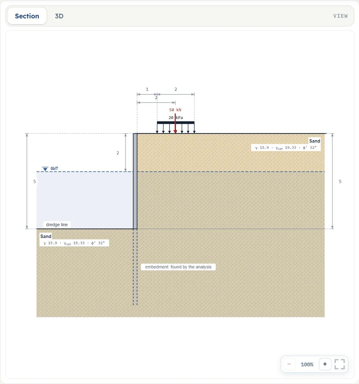
- A strip load by its body or by either edge, and a point load: along the ground, in steps of 5 cm.
Press a layer, an anchor or a load on the drawing without pulling and it opens in its form. After Analyze there are no handles and the inputs are locked; Edit inputs unlocks them and clears the results. The unit system can still be changed.
Entering the model, section by section
The Model tab has eleven sections: Model data, Soil layers, Groundwater, Wall and embedment, Terrain, Ground anchor, Surcharge, Earthquake, Design factors, Sheet pile and Design code. Each opens when you click its title; Next and Back at the foot walk you through them, and Analyze waits in the bar below. Where a unit is shown twice or three times, such as m · ft, the units are those of SI · kN, SI · tf and US in turn, and equal ones are merged. Defaults are shown in SI.
Model data
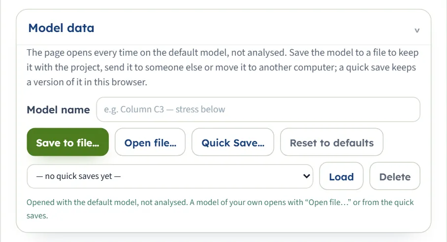
The first section holds the model name, Save to file…, Open file…, Quick Save… with its list and Load and Delete, and Reset to defaults, as described in the workspace guide. After Analyze the model is locked, and so are Reset, Open and Load until you press Edit inputs.
Soil layers
A form over a table. The New layer form takes the name, thickness, unit weights, friction angle and subgrade reaction of one layer; + Add layer puts it at the bottom of the table, and a counter shows how many of the four layers there are. The table lists every layer with a swatch of its colour on the drawing. Press a row (or the layer on the drawing) to change it in the form, which then reads Editing · Layer 2 and offers Done and Delete layer; changes apply as they are entered. × takes a layer out. The first item, Sand-1, is already in the table with the defaults; the form for a new layer opens with a thickness of 2 m.
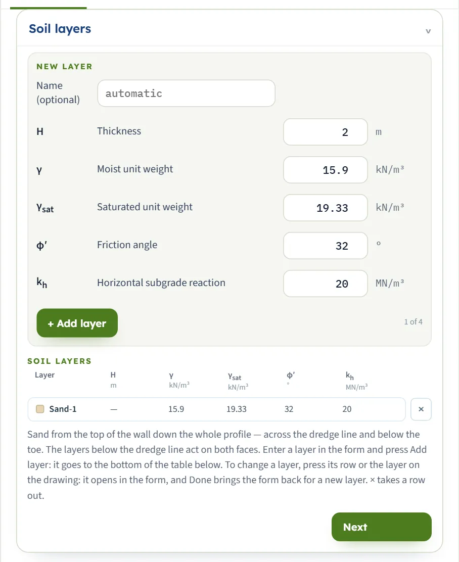
| Field | Default | What to enter |
|---|---|---|
| Name | automatic | Shown in the table and on the drawing: Sand-1, Sand-2 … (optional) |
| Thickness H m · ft | 5 (first layer); 2 (form) | From the top of the wall down. At least 0.1 m. The last layer has no thickness: it runs on below the toe, and its row shows a dash. |
| Moist unit weight γ kN/m³ · t/m³ · pcf | 15.9 | At least 1. Used above the water table. |
| Saturated unit weight γsat kN/m³ · t/m³ · pcf | 19.33 | At least 1, and above the unit weight of water, 9.81 kN/m³, for a layer that reaches below the water table. |
| Friction angle φ′ ° | 32 | From 15° to 45°. It gives Ka and Kp of the layer. |
| Dry unit weight γd kN/m³ · t/m³ · pcf | 15 | At least 1 and not above γsat. Shown only when the earthquake check is on with free pore water. |
| Horizontal subgrade reaction kh MN/m³ · t/m³ · pci | 20 | At least 0.1 MN/m³. It gives the stiffness of the soil springs of the displacement estimate; the embedment and the moment do not use it. |
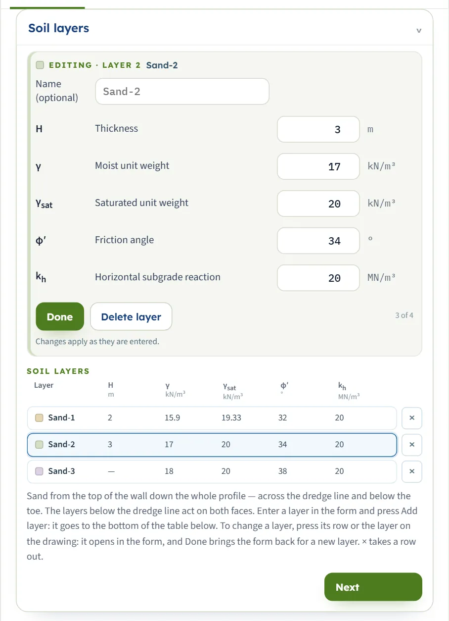
The thicknesses are measured from the top of the wall and add up down the profile; the dredge line is where L puts it, so a layer may begin above it and run on below it, and a layer wholly below it acts on both faces. The profile in the picture (2 m, 3 m, then the last layer) has its dredge line at the end of the second layer.
Groundwater
Water table has None and Present; the unit weight of water, 9.81 kN/m³, is shown. With Present, Level in the excavation has Same as retained side, the default, and Different level, which asks for the depth Dw,exc . With None the saturated unit weights are not used.
| Field | Default | What to enter |
|---|---|---|
| Water table depth (retained side) Dw m · ft | 2 | Measured down from the top of the wall. Zero or more. |
| Water level in the excavation Dw,exc m · ft | 6 | Also measured down from the top of the wall; a depth less than L puts free water in the excavation, a depth more than L a lowered level. Shown when the level is different. |
At the same level the hydrostatic pressures on the two faces cancel and only effective pressures load the wall; the drawing then shows the water standing in the excavation to the same level. With a different level each face carries the hydrostatic pressure of its own water level, and the net pressure is added. If you choose Different level and type the retained-side level, the result is the same as for the same level and a note says so.
Wall and embedment
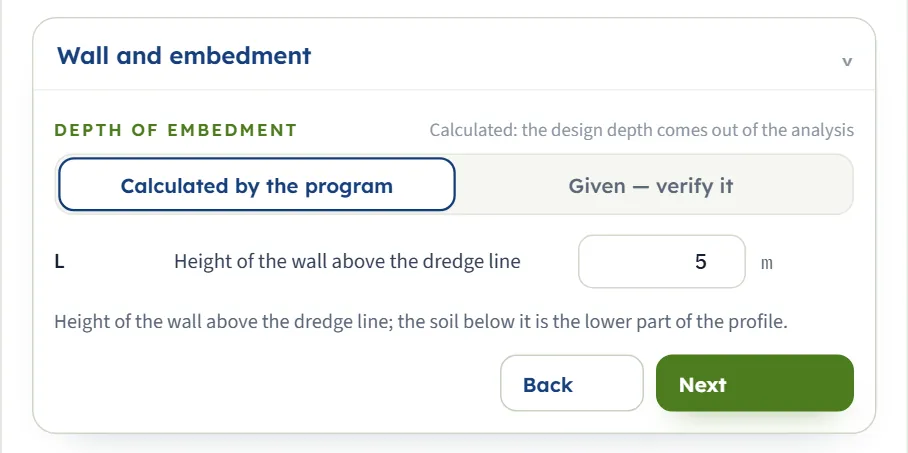
The height L and the choice Depth of embedment: Calculated by the program (the design depth comes out of the analysis) or Given — verify it, which shows the depth D and verifies it.
| Field | Default | What to enter |
|---|---|---|
| Height of the wall above the dredge line L m · ft | 5 | At least 0.5 m. The soil below it is the lower part of the profile. |
| Depth of embedment below the dredge line D m · ft | 5 | At least 0.1 m. Shown when the embedment is Given. |
Terrain
Retained ground surface: Level or Sloping, rising away from the wall without end. Sloping asks for the angle β (default 15°, from 0° to 45°).
Ground anchor
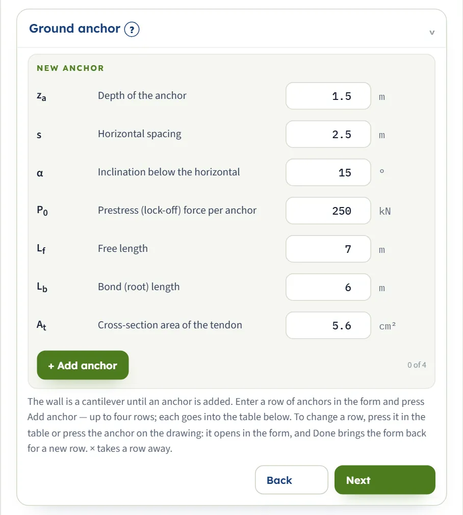
The wall is a cantilever until you add an anchor. Once you add the first row, a Tendon choice (Strand or Bar, each with a ? that opens a help window) appears above the form. Fill the New anchor form and press + Add anchor: up to four rows, listed in a table below; press a row or the anchor on the drawing to change it. Rows are taken in order of depth.
| Field | Default | What to enter |
|---|---|---|
| Depth of the anchor za m · ft | 1.5 (rows 2 to 4: 3, 3.8, 4.5) | Below the top of the wall, above the dredge line: 0 ≤ za < L. Rows stand at least 0.25 m apart. |
| Horizontal spacing s m · ft | 2.5 | At least 0.5 m. Each anchor carries the reaction of its row over this width. |
| Inclination below the horizontal α ° | 15 | From 0° to 60°. |
| Prestress (lock-off) force per anchor P0 kN · tf · kip | 250 | Zero or more. It starts the anchor spring of the displacement estimate. |
| Free length Lf m · ft | 7 | At least 0.5 m. |
| Bond (root) length Lb m · ft | 6 | At least 0.5 m. It places the bond zone. |
| Cross-section area of the tendon At cm² · in² | 5.6 | Gives the stiffness of the anchor with its free length. |
Surcharge
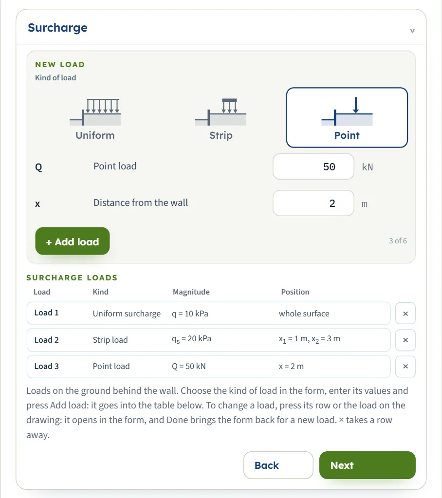
New load: choose Uniform, Strip or Point, fill its values and press + Add load: up to six loads, listed in a table with their kind, magnitude and position. Loads stand on the ground behind the wall. Press a row or the load on the drawing to change it.
| Field | Default | What to enter |
|---|---|---|
| Uniform surcharge on the retained surface q kPa · t/m² · ksf | 10 | Zero or more. |
| Strip load qs kPa · t/m² · ksf | 20 | The pressure the strip carries. |
| Near edge from the wall / far edge from the wall x1, x2 m · ft | 1 / 3 | 0 ≤ x1 < x2. A strip placed at 0 m is taken at 0.30 m by the module. |
| Point load Q kN · tf · kip | 50 | Zero or more; it must be above zero to analyse. |
| Distance from the wall x m · ft | 2 | Zero or more. |
| Combination factor in the earthquake ψ2 | 1 | From 0 to 1; it scales the load in the earthquake check. Shown when the earthquake check is on. |
Earthquake
Seismic situation: Not checked or Pseudo-static check (Mononobe–Okabe). With the check on, Pore water during the earthquake has Moves with the soil and Free (very permeable), each with a ?; free water asks for the dry unit weight γd of each layer. The coefficients are yours, from your seismic code.
| Field | Default | What to enter |
|---|---|---|
| Horizontal seismic coefficient kh | 0.15 | From 0 to 0.6. |
| Vertical seismic coefficient kv | 0.075 | From 0 to 0.4. Both senses, up and down, are checked. |
Design factors
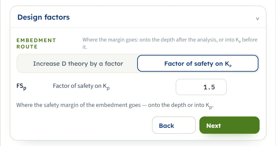
Embedment route: Increase D theory by a factor (the depth factor f) or Factor of safety on Kₚ (the factor FSp). See the next section.
| Field | Default | What to enter |
|---|---|---|
| Depth increase factor f | 1.3 | From 1 to 1.6. Shown with the route that increases Dtheory. |
| Factor of safety on Kp FSp | 1.5 | From 1 to 3. Shown with the route that reduces Kp. |
Sheet pile
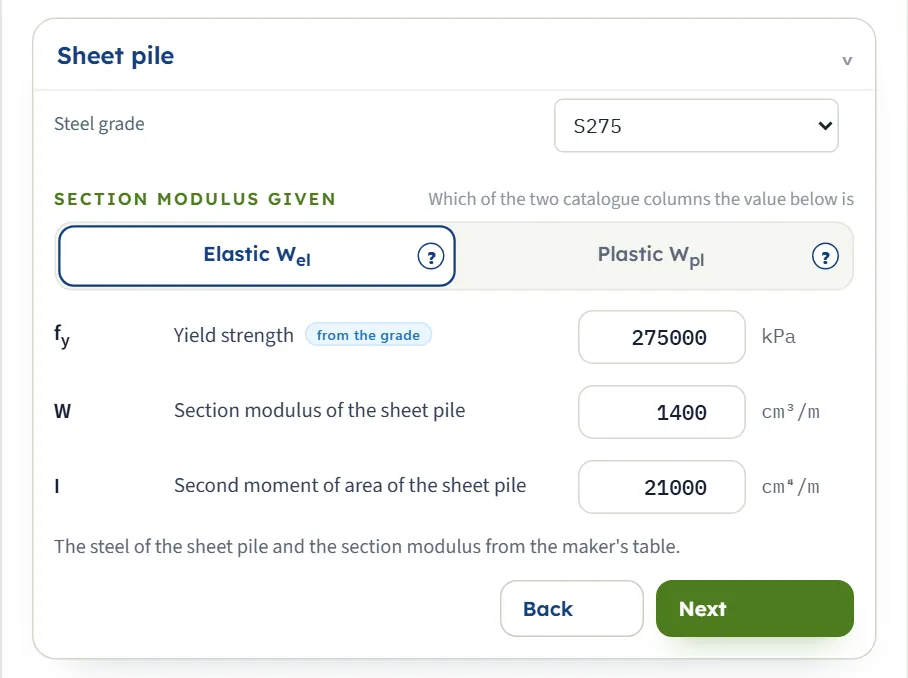
Steel grade: S235, S275, S355 or Typed. Section modulus given: Elastic Wel or Plastic Wpl, each with a ?. The yield strength follows the grade until you type a value of your own.
| Field | Default | What to enter |
|---|---|---|
| Yield strength fy kPa · t/m² · ksf | 275000 kPa, from the grade | Filled from the grade (S235, S275, S355); type your own over it, or choose Typed. |
| Section modulus of the sheet pile W cm³/m · in³/ft | 1400 | Per metre of wall, from the maker’s table; the elastic or the plastic column as chosen. May be left empty. |
| Second moment of area of the sheet pile I cm⁴/m · in⁴/ft | 21000 | Per metre of wall; used for the displacement estimate. |
Design code
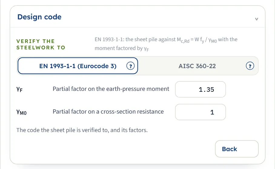
Verify the steelwork to: EN 1993-1-1 (Eurocode 3) or AISC 360-22; with AISC, Design method LRFD or ASD. Each choice has a ? that opens a help window with its equation.
| Field | Default | What to enter |
|---|---|---|
| Load factor on the earth pressure (AISC, LRFD) γH | 1.6 | From 1 to 2. |
| Partial factor on the earth-pressure moment (EN 1993-1-1) γF | 1.35 | From 1 to 1.6. |
| Partial factor on a cross-section resistance (EN 1993-1-1) γM0 | 1 | From 1 to 1.3. |
Choosing the embedment, the wall type and the code
Four decisions shape the answer.
The embedment route
| Route | Effect |
|---|---|
| Increase D theory by a factor | The diagram is built with the full Kp; Dtheory is the depth that balances it exactly, and Ddesign = f × Dtheory. The moment is that of the balanced diagram, so f changes the depth only. f = 1.3: Dtheory = 5.403 m, Ddesign = 7.023 m, Mmax = 209.6 kN·m/m. f = 1.2 gives 6.483 m and f = 1.5 gives 8.104 m, with the same moment. |
| Factor of safety on Kₚ | Kp is divided by FSp before the diagram is built, which lengthens the depth and raises the moment. The depth found is the design depth, with no further increase; do not add a depth factor on top. FS = 1.5: Dreq = Ddesign = 7.102 m, Mmax = 263.5. FS = 2: 8.837 m and 325.9. |
For this wall a factor of 1.5 on Kp asks for a deeper toe and a larger moment than a depth factor of 1.3. In the first route the first card reads Theoretical embedment depth; in the second it reads Required embedment depth.
Calculated or given depth
With Given — verify it you type D and the module verifies it. Below Dtheory the wall is not in equilibrium even with the full Kp and the analysis stops (see Messages). Above it, the module compares the given depth with the required design depth of your route and shows the factor of safety on Kp that the given depth mobilises. With D = 8 m the example gives PASS on the depth (required 7.023 m, FSp,mob = 1.762); the moment is the larger of the design diagram and of the diagram at the given depth, here 294.9 kN·m/m, so the sheet pile, utilisation 1.034 FAIL, now fails. A given depth that falls short is drawn in red with the required toe and the shortfall.
Cantilever or anchored
The wall is a cantilever until you add an anchor. With one row the module uses the free earth support method: the toe is free, the depth comes from the moments about the anchor and the anchor force from horizontal equilibrium. With two to four rows the wall is made determinate by hinges at the anchors below the uppermost, and the part below the lowest anchor is designed by free earth support about it; this idealisation is applied to the limit-equilibrium diagram of the module. Anchors shorten the embedment and cut the moment: for the example with one anchor at 1.5 m the module gives Dtheory = 1.928 m, Ddesign = 2.506 m, Mmax = 40.17 kN·m/m; with a second at 3 m, 1.662 m, 2.161 m and 19.06 kN·m/m.
The code
EN 1993-1-1: the design moment is MEd = γF Mmax (default γF = 1.35), the resistance Mc,Rd = W fy / γM0, and the section modulus asked for is Wreq = MEd γM0 / fy. AISC 360-22, LRFD: Mu = γH Mmax against φb Mn with φb = 0.90; ASD: the working moment against Mn / Ωb with Ωb = 1.67. Mn is fy Wpl for a plastic modulus (taken as compact) or fy Wel at first yield. For the example the module gives Wreq = 1,029 cm³/m by EN 1993-1-1, 1,355 by LRFD and 1,273 by ASD, with utilisations 0.7349 PASS, 0.9677 PASS, near capacity and 0.9091 PASS.
Analyze and read the results
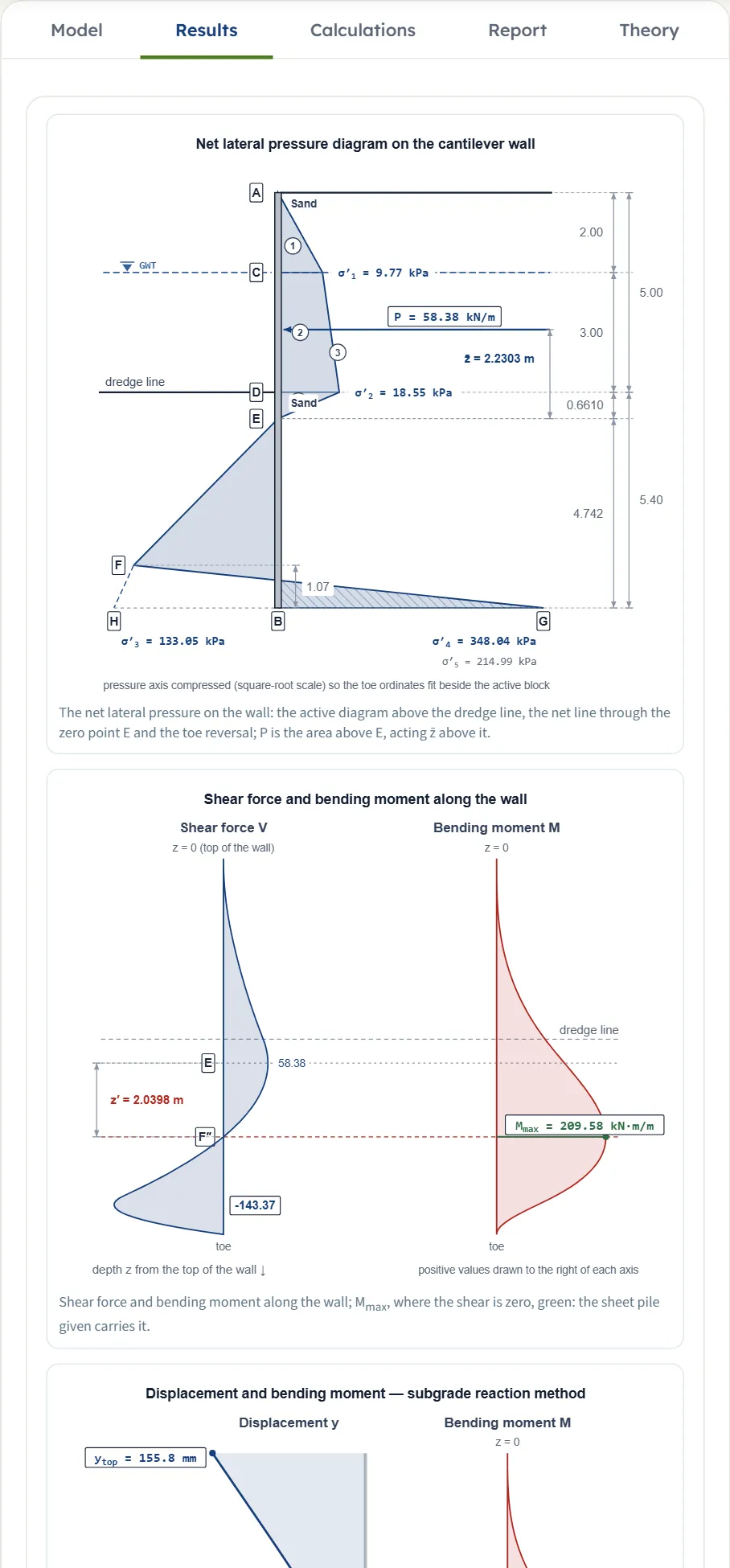
Press Analyze. The bar changes to Analysed — the sheet-pile wall calculated and says “The model is locked … Edit inputs clears the results; the unit system can still be changed.” The Model tab stays on screen: open Results to read the answer. The Section view now shows the net pressure diagram, the depths and Mmax. A button on the bar reads Notes (n) or Warnings (n), and when there are warnings a window opens by itself.
| Card | The example |
|---|---|
| Theoretical embedment depth Dtheory | 5.403 m |
| Design embedment depth Ddesign | 7.023 m |
| Maximum bending moment Mmax | 209.6 kN·m/m |
| Section modulus the sheet pile needs (EN 1993-1-1) Wreq | 1,029 cm³/m |
| Utilisation of the sheet pile given by its modulus ηsp | 0.7349 PASS |
| Top displacement of the wall (subgrade reaction, indicative) ytop | 155.8 mm |
The cards change with the case. With the factor of safety route the first card is the Required embedment depth; with a given depth the second card reads Design embedment depth — given with PASS or FAIL, and two more cards give the Required design embedment depth and the Factor of safety the given depth mobilises on Kp; with the earthquake check on a card Embedment required in the seismic situation shows DE with its verdict. If the section modulus is left empty, only Wreq is given and no section is verified.
The verdict words
The utilisation ηsp is the design moment over the resistance of the sheet pile given. It reads PASS at 1 or less and FAIL above 1; very close to 1 (0.9677 in the AISC example) it reads PASS, near capacity. The same word appears in the report.
The tables
- Values, step by step: the coefficients, the pressures, L3, P and its arm, the root L4, the toe pressures, the depths, Mmax, the design moment, Wreq, the verification and the displacements, one row per step.
- Pieces of the pressure diagram above E: each triangle and rectangle with its area and its arm above E.
- The layers down to the toe and the coefficients of their springs: kh, φ′, K0, Ka, Kp of each layer.
- Displacement, bending moment and the pressures on the two faces along the wall: the values behind the displacement diagram.
With anchors the tables add the pressures at the breaks of the diagram, the moment about the anchor for trial depths, and an anchor table with, per row, za, s, α, the force per metre F, the reaction on the tendon axis TLEM = F s / cos α, its vertical part, P0, the place of the bond zone and a PASS or FAIL on it. For the example with one anchor, F = 35.86 kN/m and TLEM = 92.8 kN.
Using the numbers
- The forces and moments are per metre of wall: kN/m and kN·m/m (tf/m and tf·m/m in SI · tf; kip/ft and kip·ft/ft in US); the section modulus is per metre of wall too.
- Mmax is the characteristic moment of the theoretical diagram; the factor of the code is applied once, in the design moment.
- The displacement is an order-of-magnitude estimate on elastic springs.
- Changing the unit system after Analyze re-states the cards, the Section and Results drawings, the tables and the working in the new units; the 3D view keeps its labels in m and kN.
The Calculations tab, the report and the Theory tab
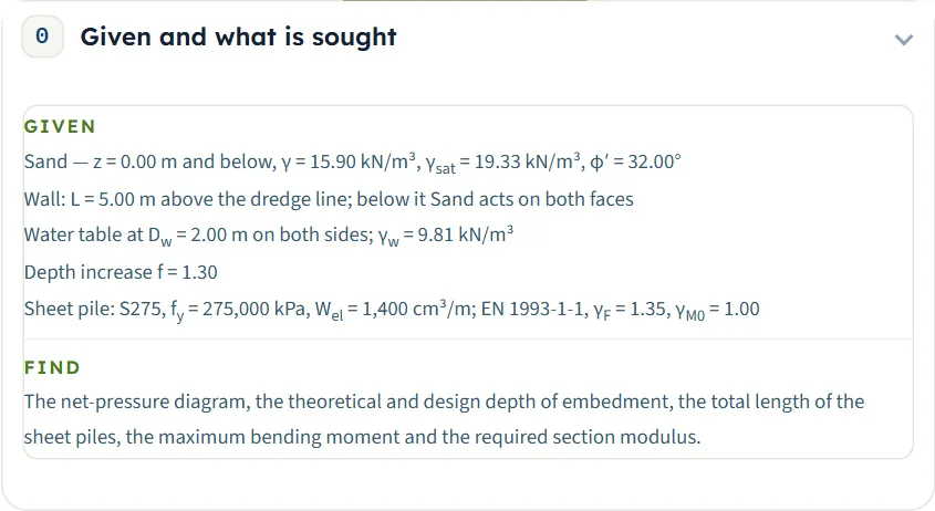
The Calculations tab starts with Given and what is sought and writes the working in numbered steps with your numbers, ending with the answer. For the cantilever wall of the example the steps are:
- Earth-pressure coefficients — Ka and Kp of each layer.
- Active pressure above the dredge line — at every boundary of the profile.
- Net pressure below the dredge line — L3, the zero point E.
- Resultant of the active diagram and its arm about E — P and z̄, with the table of pieces.
- Toe intercept and the coefficients of the embedment equation — σ′5 and the four coefficients.
- Solve the embedment equation — the root L4, with the residual and a graph.
- Pressures at the toe and the toe block — σ′3, σ′4, L5 and the closing check.
- Theoretical and design depth of embedment — the depths and the total length (with the safety route, Required and design depth).
- Maximum bending moment — z′ and Mmax, with the shear and moment diagrams.
- Take the design moment — MEd (for AISC LRFD, Take the required moment).
- Sheet pile — the section modulus asked for — Wreq.
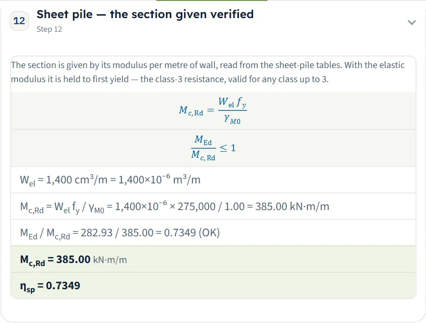
- Sheet pile — the section given verified — Mc,Rd and ηsp.
- Wall displacement — subgrade reaction method — the estimate on springs.
With anchors the steps from the embedment on change: the depth by free earth support, the moment, and a step Ground anchors — their forces and the place of their bond zones. With the earthquake check on, steps are added for the seismic coefficients, the hydrodynamic pressure of free water, the embedment and moment in the seismic situation and the sheet pile in it. Then come Notes and assumptions and the Answer.
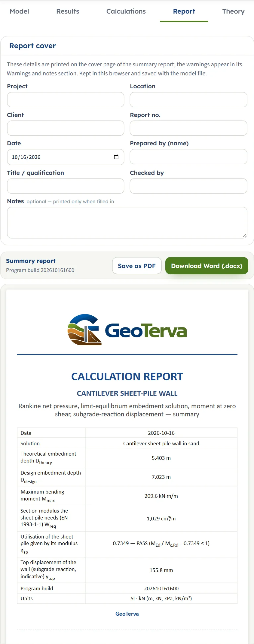
The report
In the Report tab fill in the cover (project, location, client, report number, date, prepared by, title or qualification, checked by, and optional notes), kept in this browser and saved with the model file. Save as PDF and Download Word (.docx) produce the summary report.
The report has seven parts: 1 Introduction and scope, 2 Input data, 3 Calculation (3.1 to 3.13 for a cantilever wall), 4 Results, 5 Assumptions and notes, 6 Summary and 7 References, with the section drawing and the diagrams.
The Theory tab
The Theory tab has nineteen sections: Sheet-pile walls and this module; How a cantilever wall moves; Active pressure above the dredge line; The net pressure below the dredge line; Equilibrium: the embedment equation; The depth of embedment; The maximum bending moment; No water table; Water at different levels on the two faces; Verifying the sheet pile to EN 1993-1-1; Verifying the sheet pile to AISC 360-22; The sloping retained surface; The anchored wall; The seismic situation; The displacement of the wall; A worked example, by the module; The opening wall, verified to EN 1993-1-1; What the module assumes; and References.
Worked example: the module’s own example
The module opens on this example, so you can follow the numbers on your own screen.
| Input | Value |
|---|---|
| Soil layers: Sand-1 | γ = 15.9, γsat = 19.33 kN/m³; φ′ = 32° |
| Groundwater: Water table | Present, Dw = 2 m, same level on both faces |
| Wall and embedment: Wall | L = 5 m, depth calculated |
| Design factors: Route | Depth factor f = 1.3 |
| Sheet pile, Design code: Steel | S275 (fy = 275,000 kPa), Wel = 1,400 cm³/m; EN 1993-1-1, γF = 1.35, γM0 = 1.00 |
Step 1: the coefficients
Ka = tan²(45° − 32°/2) = 0.3073 and Kp = tan²(45° + 32°/2) = 3.2546.
Step 2: the active pressure above the dredge line
At the water table, σ′v = 15.9 × 2 = 31.80 kPa and σ′1 = 0.3073 × 31.80 = 9.77 kPa. At the dredge line, with γ′ = 19.33 − 9.81 = 9.52 kN/m³, σ′v = 31.80 + 9.52 × 3 = 60.36 kPa and σ′2 = 0.3073 × 60.36 = 18.55 kPa.
Step 3: the zero point
Below the dredge line the net pressure falls with the slope γ′(Kp − Ka) = 9.52 × 2.9473 = 28.06 kPa per m, so L3 = 18.55 / 28.06 = 0.6610 m.
Step 4: the resultant
Four pieces: ½ × 9.77 × 2.00 = 9.771 kN/m at an arm of 4.328 m above E; 9.77 × 3.00 = 29.31 at 2.161 m; ½ × 8.78 × 3.00 = 13.16 at 1.661 m; ½ × 18.55 × 0.6610 = 6.129 at 0.4407 m. So P = 58.38 kN/m and z̄ = 130.19 / 58.38 = 2.2303 m.
Step 5 and 6: the embedment equation
σ′5 = 60.36 × 3.2546 + 28.06 × 0.6610 = 214.99 kPa. The coefficients are A1 = 7.66, A2 = 16.64, A3 = 151.33 and A4 = 230.63, and
Step 7 to 9: the depths and the moment
σ′3 = 4.742 × 28.06 = 133.05 kPa, σ′4 = 214.99 + 28.06 × 4.742 = 348.04 kPa and L5 = 1.07 m, which lies between 0 and L4, so the diagram closes. Dtheory = 0.6610 + 4.742 = 5.40 m, Ddesign = 1.30 × 5.40 = 7.02 m and the total length is 5.00 + 7.02 = 12.02 m. The shear is zero at z′ = √(2 × 58.38 / 28.06) = 2.0398 m below E, where
Step 10 to 12: the sheet pile
MEd = 1.35 × 209.58 = 282.93 kN·m/m; Wreq = 282.93 × 1.00 / 275,000 = 1,028.83 cm³/m; Mc,Rd = 1,400×10⁻⁶ × 275,000 / 1.00 = 385.00 kN·m/m, so ηsp = 282.93 / 385.00 = 0.7349, PASS. The displacement of the top is 155.8 mm toward the excavation.
These are the cards of the Results tab.
Other unit systems
The default example in US gives Dtheory = 17.73 ft, Ddesign = 23.04 ft, Mmax = 47.11 kip·ft/ft, Wreq = 19.14 in³/ft and ηsp = 0.7349 PASS: the same wall (5.403 m is 17.73 ft; 209.6 kN·m/m is 47.11 kip·ft/ft). Two checks with values typed in the other systems and recomputed by hand:
- US. One layer of 110 pcf sand at 30°, no water, L = 15 ft, depth factor 1.3: Ka = 1/3, and the hand calculation gives Dtheory = 15.06 ft, Ddesign = 19.58 ft and Mmax = 46.41 kip·ft/ft. The module gives 15.06 ft, 19.58 ft and 46.41 kip·ft/ft.
- SI · tf. One layer of 1.7 t/m³ sand at 30°, no water, L = 4 m, f = 1.4: by hand Dtheory = 4.017 m, Ddesign = 5.624 m and Mmax = 13.60 tf·m/m. The module gives 4.017 m, 5.624 m and 13.60 tf·m/m.
How each input changes the answer
Each row changes one thing in the example (cantilever, one layer of 15.9 / 19.33 kN/m³ sand at 32°, L = 5 m, water table 2 m on both faces, f = 1.3, S275 with Wel = 1,400 cm³/m, EN 1993-1-1 with γF = 1.35) and runs the module again. The numbers are the ones the module gives. Each result is Dtheory / Ddesign in m on the first line, then Mmax in kN·m/m and the utilisation ηsp of the sheet pile given, with the verdict word.
| Change | Result |
|---|---|
| The default example The reference | 5.403 / 7.023 m 209.6 · 0.7349 PASS |
| L = 4 m A lower wall: everything falls | 4.438 / 5.769 m 114.9 · 0.4029 PASS |
| L = 6 m The moment rises by more than half and the sheet pile no longer carries it | 6.352 / 8.258 m 342.9 · 1.202 FAIL |
| φ′ = 28° A smaller friction angle: more active and less passive pressure | 6.696 / 8.705 m 293.8 · 1.030 FAIL |
| φ′ = 36° The opposite | 4.401 / 5.721 m 153.0 · 0.5366 PASS |
| γ = 18, γsat = 20 kN/m³ A heavier sand raises the pressures | 5.518 / 7.174 m 238.1 · 0.8349 PASS |
| Water table: None The depth falls by about a metre; the moment is about the same | 4.528 / 5.887 m 212.1 · 0.7437 PASS |
| Dw = 4 m A lower water table gives more effective weight above it: larger pressures | 5.866 / 7.626 m 256.6 · 0.8996 PASS |
| Dw = 1 m A higher one gives smaller pressures | 5.037 / 6.548 m 173.1 · 0.6070 PASS |
| Different level, Dw,exc = 4 m Free water 1 m deep in the excavation, 2 m lower than behind the wall: the net water pressure is added | 7.879 / 10.24 m 510.0 · 1.788 FAIL |
| Change | Result |
|---|---|
| f = 1.2 Only the design depth changes | 5.403 / 6.483 m 209.6 · 0.7349 PASS |
| f = 1.5 Only the design depth changes | 5.403 / 8.104 m 209.6 · 0.7349 PASS |
| Factor of safety FSp = 1.5 on Kp The first card is the required depth; moment and depth both rise | 7.102 / 7.102 m 263.5 · 0.9241 PASS |
| FSp = 2.0 A larger moment: the sheet pile fails | 8.837 / 8.837 m 325.9 · 1.143 FAIL |
| W = 1,000 cm³/m The demand is the same; the section is too light | 5.403 / 7.023 m 209.6 · 1.029 FAIL |
| γF = 1.0 A smaller design moment: lower utilisation | 5.403 / 7.023 m 209.6 · 0.5444 PASS |
| AISC 360-22, LRFD γH = 1.6 on the moment against φb Mn | 5.403 / 7.023 m 209.6 · 0.9677 PASS |
| AISC 360-22, ASD The working moment against Mn / 1.67 | 5.403 / 7.023 m 209.6 · 0.9091 PASS |
| Change | Result |
|---|---|
| Uniform surcharge 10 kPa Adds Ka q above the dredge line and Kp q to the passive pressure at the toe | 6.149 / 7.993 m 305.5 · 1.071 FAIL |
| Uniform surcharge 20 kPa About twice the increase | 6.819 / 8.864 m 410.9 · 1.441 FAIL |
| Strip load 20 kPa, 1 m to 3 m The pressure comes from the elastic solution, doubled for a rigid wall | 6.315 / 8.209 m 344.2 · 1.207 FAIL |
| Point load 50 kN at 2 m A smaller effect than the strip | 5.741 / 7.464 m 256.0 · 0.8975 PASS |
| Sloping surface, β = 15° The horizontal part of the sloping Rankine pressure | 5.642 / 7.335 m 232.1 · 0.8137 PASS |
| β = 25° Closer to φ′: much larger pressures | 6.346 / 8.249 m 305.5 · 1.071 FAIL |
| A second layer below the dredge line: 18 / 20 kN/m³, φ′ = 38° A stronger sand at the toe shortens the wall | 4.251 / 5.526 m 172.3 · 0.6041 PASS |
| Change | Result |
|---|---|
| One anchor row at 1.5 m (s = 2.5 m, 15°) The wall is held at the anchor: a third of the cantilever depth and a fifth of the moment | 1.928 / 2.506 m 40.17 · 0.1408 PASS |
| One anchor row at 3 m A lower anchor: a shallower toe and about half the moment | 1.414 / 1.838 m 21.66 · 0.07594 PASS |
| Two rows, at 1.5 m and 3 m Hinge idealisation: the moment halves again | 1.662 / 2.161 m 19.06 · 0.06685 PASS |
| Embedment given, D = 8 m The depth passes; the moment is that of the given depth and the sheet pile fails | 5.403 / 8.000 m 294.9 · 1.034 FAIL |
| Embedment given, D = 5.5 m Between Dtheory and the required depth: the depth fails | 5.403 / 5.500 m 212.5 · 0.7450 PASS |
The pattern follows the formulas. The depth and the moment follow Ka, Kp, the effective weights and the loads; the depth factor leaves the moment alone but a factor of safety on Kp raises both; an anchor holds the top of the wall and the embedment becomes a question of the toe alone. With the earthquake check on, the card DE compares the depth the seismic pressures need with the design depth: for the example with kh = 0.15 it reads 9.987 m FAIL against 7.02 m, and with kh = 0.05 and kv = 0 the check passes.
Messages: when the module stops, and what it notes
The module checks the numbers before it calculates. When one cannot be used it stops and nothing is calculated.
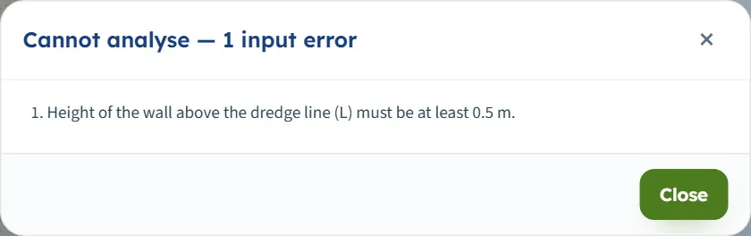
- A value outside its limits opens Cannot analyse — 1 input error (or 2, 3 …) listing each message, and the box is marked in red.
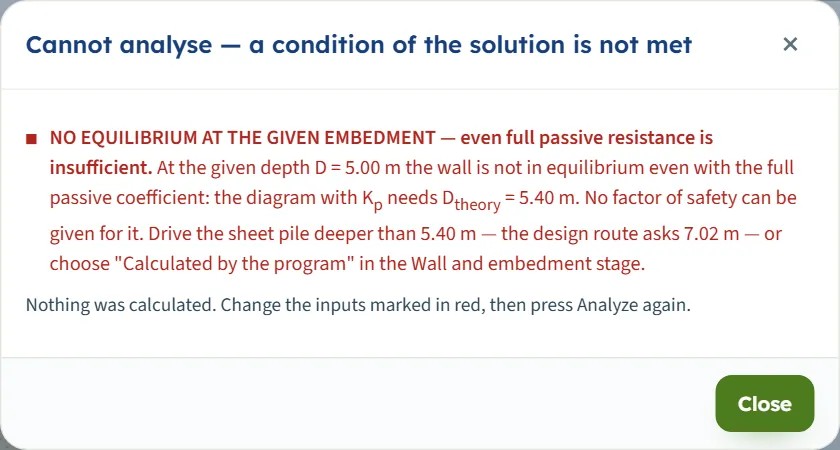
- A condition of the solution that is not met opens Cannot analyse — a condition of the solution is not met, which ends “Nothing was calculated. Change the inputs marked in red, then press Analyze again.”
- The limits are shown in the unit system chosen.
| When | Message |
|---|---|
| Stop: A value outside its limits | “Height of the wall above the dredge line (L) must be at least 0.5 m.” · “Friction angle (φ′1) must be at least 15°.” or “… at most 45°.” · “Moist unit weight (γ1) must be at least 1 kN/m³.” · “Depth increase factor (f) must be at least 1.” · “Factor of safety on Kp (FSp) must be at least 1.” or “… at most 3.” · “Water table depth (retained side) (Dw) must be at least 0 m.” · “Depth of embedment below the dredge line (D) must be at least 0.1 m.” · “Inclination below the horizontal (α) must be at most 60°.” · “Horizontal seismic coefficient (kh) must be at most 0.6.” · “Combination factor in the earthquake (ψ2) must be at most 1.” |
| Stop: The level in the excavation is Different but empty | “Water level in the excavation (Dw,exc) is missing.” |
| Stop: Saturated unit weight at or below that of water, with a water table | “Sand: saturated unit weight must exceed γw. Below the water table the overburden uses γ′ = γsat − γw. Enter the saturated unit weight.” |
| Stop: An anchor at or below the dredge line | “The anchor must stand above the dredge line. za is its depth below the top of the wall: 0 ≤ za < L.” |
| Stop: Two anchor rows less than 0.25 m apart | “Anchor row 2: two rows of anchors stand at nearly the same depth. The rows need at least 0.25 m between them to be separate supports.” |
| Stop: The slope as steep as the friction angle | “Sand: the slope angle β = 40° must be smaller than φ′ = 32°.” followed by the reason: a sand does not stand on a slope steeper than its friction angle. |
| Stop: A strip or point load with a sloping surface | “Strip and point loads cannot be combined with a sloping retained surface.” Use uniform loads, or a level surface. |
| Stop: A strip with its far edge not beyond its near edge, or a point load of zero | “Load 1 (strip load): the strip must have its far edge beyond its near edge.” · “Load 1 (point load): the point load must be greater than zero.” |
| Stop: Free pore water with a dry unit weight above the saturated one | “Sand: the dry unit weight γd must be greater than zero and not above γsat.” |
| Stop: A given depth below Dtheory | “NO EQUILIBRIUM AT THE GIVEN EMBEDMENT — even full passive resistance is insufficient.” It names the depth the diagram needs and the design route’s depth. Drive the sheet pile deeper or choose Calculated by the program. |
| Stop: A head the sand cannot balance | “No depth of embedment balances the diagram with the levels entered.” Happens, for instance, with the example and the excavation level at the top of the wall (Dw,exc = 0). |
When more than one value is wrong the window lists them together. The layer or row number is part of the symbol: φ′1 belongs to layer 1.
Warnings
A warning marks a result that the module calculates but that fails a check. The button on the bar reads Warnings (n), and the window opens by itself after Analyze:
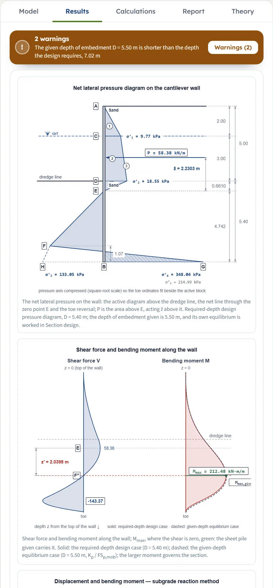
- The sheet pile does not carry the moment: “The sheet pile given does not carry the design moment: MEd / Mc,Rd = 1.07 …”, with the resistance, the demand and the section modulus the wall asks for. Take a heavier sheet pile or a higher grade. In the earthquake the same message is about the seismic moment.
- Large displacement: “ytop = 259.3 mm, 5.2 % of the retained height L …” raised at 5 % of L. The estimate is a small-displacement idealisation; read it as an order of magnitude.
- The embedment is too short for the earthquake: “The design embedment is too short for the seismic situation: DE = 9.99 m > Ddesign = 7.02 m …”
- A given depth that falls short: “The given depth of embedment D = 5.50 m is shorter than the depth the design requires, 7.02 m. At the given depth the passive resistance mobilises a factor of safety of only 1.03 on Kp …”, with a note that the displacement is then indicative only.
Notes
A note states an assumption of the calculation; the button reads Notes (n) when nothing fails. The default example carries three: the sheet pile is checked on the modulus given as the modulus of the whole wall (a U-pile wall may have it reduced where the interlocks can slip, a Z-pile wall carries the full value); the moment is factored by γF before the code check; and the displacement is estimated on springs and indicative. Other notes appear with the case:
- The factor of safety route: the factor was applied to Kp before the diagram was built, and no depth factor is to be added on top.
- Water at different levels: the hydrostatic pressures on the two faces are independent; seepage is not part of the model. Equal levels under Different level give a note that the result is that of the same level.
- Loads and slope: the uniform surcharge adds Ka q above the dredge line and Kp q at the toe on the retained side; strip and point loads come from the elastic solution for a rigid wall and the equilibrium is solved numerically; a slope uses the horizontal part of the sloping active pressure.
- Anchors: the anchor table gives the reaction TLEM of the design diagram, and the vertical component (9.61 kN/m for the one-anchor example) is listed for your axial and toe-bearing design; TLEM is a reaction, not a lock-off or a test load.
- Plastic modulus: used with the section taken as class 1 or 2.
- No section modulus: the modulus needed is found and no section is verified.
- AISC with an EN grade: used by its yield strength.
Good practice and common mistakes
- Know which face is which. The retained soil is on the right of the drawing, the excavation on the left; the dredge line is the excavation level.
- Water at the same level on both faces is a design statement: the drawing shows free water standing in the excavation. If the excavation is dewatered, choose Different level and enter the level there.
- Enter the saturated unit weight above 9.81 kN/m³ for any layer that reaches below the water table.
- Choose the route once. With the factor of safety on Kp do not add a depth factor on top; the depth found is the design depth.
- Read Mmax as characteristic. The code factor is applied in the design moment; the section modulus is per metre of wall.
- Give the section modulus of the whole wall, from the maker’s table, and take the interlocks and the shear of the wall from the maker’s data.
- With anchors, use the reaction TLEM, the vertical component and the bond zone from the anchor table for the design of the tendons and the toe.
- Use the earthquake check to compare: the depth DE and the seismic moment are shown next to the static design.
- Do not rely on the handles after Analyze: they are gone and the inputs are locked until Edit inputs.
- Keep the model: the page opens on the default every time; use Save to file… or Quick Save…, and the report as the record.
Frequently asked questions
How is the embedment of a cantilever sheet pile in sand found?
The active pressure above the dredge line and the net pressure below it (active less passive) are balanced by the equilibrium of forces and moments about the toe, with the toe pressures reversed over a block L5. That gives an equation of the fourth degree in the depth L4 of the toe below the zero point E, which the module solves. Dtheory = L3 + L4; for the example it is 5.403 m.
What is the difference between the depth factor and the factor of safety on Kp?
The depth factor multiplies the balanced depth: the example goes from 5.403 m to 7.023 m at 1.3 and the moment is unchanged. The factor of safety divides Kp before the diagram is built, so the depth and the moment both rise: 7.102 m and 263.5 kN·m/m at 1.5.
Where is the maximum moment, and is it factored?
At the depth z′ below E where the shear is zero; it is the characteristic moment of the balanced diagram, 209.6 kN·m/m for the example. The code factor (γF = 1.35 for EN 1993-1-1, γH = 1.6 for AISC LRFD, none for ASD) is applied once, to get the design moment.
How do I enter a wall with a lowered water level in the excavation?
In Groundwater choose Present, then Different level, and enter the depth Dw,exc below the top of the wall. A depth greater than L is below the dredge line. The net hydrostatic pressure is added, with no seepage.
How many anchors can I add, and how are they treated?
Up to four rows. One row is designed by free earth support: the toe is free and the anchor force comes from horizontal equilibrium. Two or more rows use a hinge idealisation on the limit-equilibrium diagram. Each row has a depth, a spacing, an inclination, a lock-off load and lengths; the anchor table gives the reaction per anchor.
How do I verify an embedment I already have?
Choose Given — verify it and type D. Below Dtheory the analysis stops; above it the module shows whether the depth reaches the required design depth and the factor of safety on Kp it mobilises, and it draws the shortfall in red.
Which sheet-pile checks does the module make?
The sheet pile is verified in bending on the section modulus per metre of wall to EN 1993-1-1 (resistance W fy / γM0) or AISC 360-22 (LRFD or ASD). Leave the modulus empty and the module gives the modulus you need.
Can I drag things on the drawing?
Before Analyze: the water levels, the layer boundaries, the toe (which makes the embedment given), and strip and point loads. After Analyze there are no handles; press Edit inputs.
Does the module remember my inputs?
No: it opens on the default example every time; only the unit system you chose is remembered, and the default values are shown in it (5 m reads 16.4042 ft in US). Save to file keeps the model with the project and Quick Save keeps versions in the browser.
What does the earthquake check do?
It replaces the Rankine coefficients by Mononobe–Okabe ones with the coefficients kh and kv you give (both senses of kv), with restrained or free pore water, and compares the embedment the seismic pressures need, DE, with the design embedment, and the sheet pile with the seismic moment.
Which units does it use?
SI · kN, SI · tf or US, switchable in the header at any time. The default example gives Ddesign = 7.023 m, 7.023 m or 23.04 ft; Mmax is 209.6 kN·m/m, 21.37 tf·m/m or 47.11 kip·ft/ft.
What if the sheet pile fails?
The utilisation reads FAIL and a warning says what the wall asks for. Choose a heavier section or a higher grade, or reduce the moment with anchors, a lower wall or a stronger sand.