

What the module calculates
Anchored sheet pile on layered soil designs a sheet-pile wall in a profile of sand and clay layers, down the whole wall. The wall may be a cantilever or be held by up to four rows of inclined ground anchors. The module builds the pressure on both faces of the wall layer by layer, finds the embedment below the dredge line by limit equilibrium, gives the anchor forces, the maximum bending moment and the depth where it acts, and then checks the anchors (free length and bond), the steel section, the bottom heave of a clay base, the displacement of the wall and, if you switch it on, the earthquake.
Every layer is sand or clay, and a clay is analysed in the short term (undrained, in total stress with cu) and in the long term (drained, in effective stress with c′ and φ′). When the profile has a clay, both scenarios are run and the larger value of each result designs the wall. The pressures are Rankine pressures on a vertical wall with no wall friction:
Water stands at its own level on each face of the wall; uniform, strip and point surcharges can be listed on the retained surface; the net pressure is the retained pressure less the passive resistance of the excavation side, and the statics are solved on it: free earth support about one row of anchors, the hinge method for several rows, and the conventional toe-block method for a cantilever.
What you can describe
- A profile of up to six layers from the top of the wall down, each Sand — drained, c′ and φ′ or Clay — cu short term, c′ and φ′ long term; the layers run across the dredge line and below the toe.
- Water on the retained side and, if you wish, at a different level in the excavation.
- A cantilever, or one to four rows of anchors, each with its own depth, spacing, inclination, lock-off force, free and bond lengths.
- Uniform, strip and point surcharges (up to six loads in a list).
- An embedment calculated by the module or given by you and verified.
- The margin on the embedment: a factor on the depth, or a factor of safety on the passive pressure.
- The steel section by its modulus and grade, verified to EN 1993-1-1 or AISC 360-22.
- A bottom-heave check and a pseudo-static earthquake check.
Which module for which wall
- A wall in a single layer of sand, cantilever or anchored: Sheet pile in sand.
- A wall in undrained clay above and below the dredge line: Sheet pile in clay.
- A profile of several layers of sand and clay, or a wall held by more than one row of anchors, or the short- and long-term scenarios of a clay side by side: this module.
- The Rankine and Coulomb coefficients behind the pressures are explained in the Lateral earth pressure manuals; the loads on the retained surface in the Surcharge loads manuals.
Combine the results with your own checks of the overall stability of the excavation and, for anchored walls, of the deep-seated stability of the anchored block; the module reminds you of both in every anchored run (see Messages).
Before you start: what you need
Have these ready from your design and your ground investigation:
| What and source | Notes |
|---|---|
| The soil profile Boring logs and tests | For each layer from the top of the wall down: thickness, moist and saturated unit weight, φ′ and c′, and for a clay cu. The last layer runs on below the toe. |
| Wall height L Your design | From the top of the wall to the dredge line. At least 0.5 m. |
| The water Groundwater readings | The depth Dw of the water table on the retained side, and the level in the excavation if it differs. |
| The anchors Your design | Depth za, horizontal spacing s, inclination α, lock-off force, free length, bond length, tendon area, grout body diameter and the ultimate bond stress from your tests or tables. |
| The loads Your design loading | Uniform, strip and point loads behind the wall, with their position. |
| The sheet pile The maker’s table | Steel grade, section modulus per metre of wall and, for the displacement, the second moment of area. |
Quick start in eight steps
- Open the module and choose the units
Open Anchored sheet pile on layered soil from the Sheet-Pile Walls family. Pick SI · kN, SI · tf or US in the header; you can change it at any time.
- Describe the soil
In Soil layers fill the New layer form (sand or clay, thickness, unit weights, strength) and press + Add layer. The layers go from the top down; the last one has no thickness and runs below the toe.
- Enter the water, the wall and the anchors
In Groundwater give the water table, in Wall and embedment the height L, and in Ground anchor add the rows with + Add anchor, or remove them for a cantilever.
- Add the loads and the earthquake
In Surcharge add uniform, strip or point loads; in Earthquake switch the pseudo-static check on if you need it.
- Choose the margin and the section
In Design factors set the factor on the depth (or on the passive pressure) and the scenario of the clay; in Sheet pile and Design code give the steel and the code.
- Press Analyze
Press Analyze at the foot of the Model tab. A window lists the warnings, the bar reads Analysed, the inputs lock and the drawing shows the pressure and the design embedment. A mistake in the inputs opens Cannot analyse with the fields to correct.
- Read the results
The Results tab gives the diagrams, the values step by step, the cards and the verdicts. A Warnings button lists what needs your attention.
- Take the working and the report
The Calculations tab writes out every step with your numbers; the Report tab saves a PDF or a Word file.
The screen: views, zoom and dragging
The layout is the one every GeoTerva module shares, described in the workspace guide: the drawing on the left, the tabs Model, Results, Calculations, Report and Theory on the right. The drawing has two views, chosen above it:
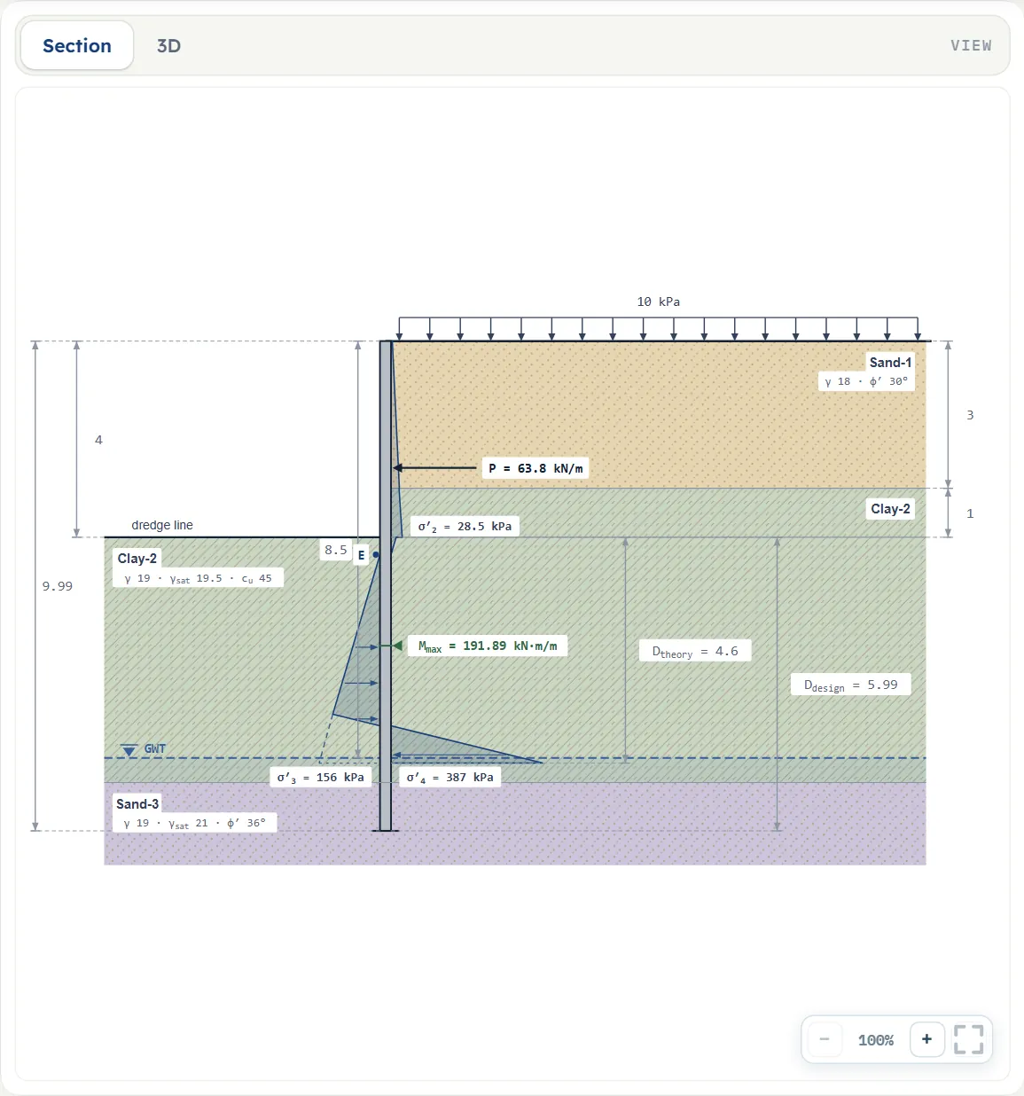
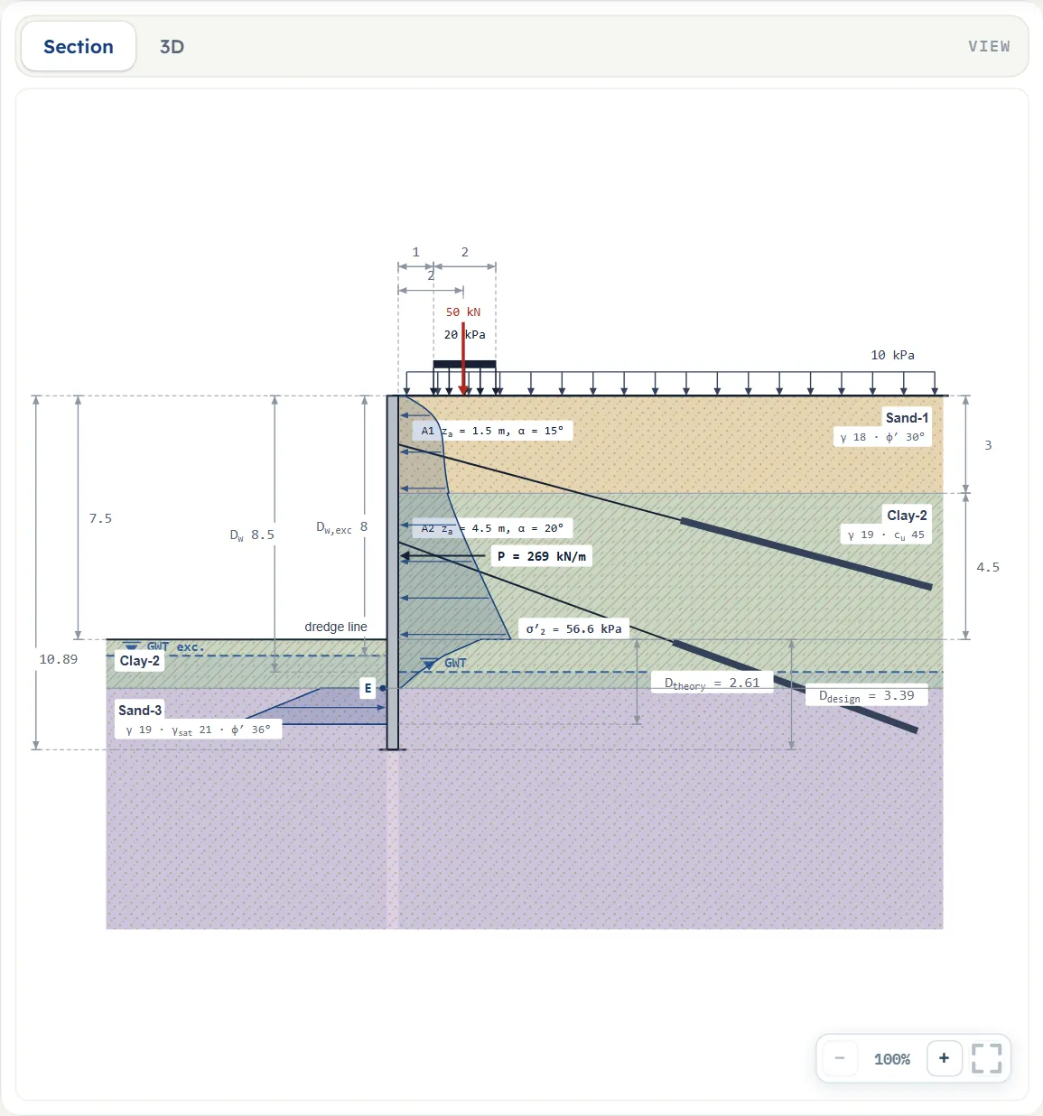
- Section is the wall with the soil layers, their unit weight and strength, the water tables, the anchors with their depth and inclination, the surcharge loads and the dimensions. It follows your inputs. After Analyze it adds the active pressure on the retained face, the resultant P with the zero-pressure point E, the theoretical and the design embedment Dtheory and Ddesign, and, for a cantilever, the reversed pressures at the toe.
- 3D is an oblique view of a length of the wall with the retained soil on one side and the excavation on the other, the anchors in their rows and the water table. After Analyze it adds the design embedment and a line with Mmax, Wreq and the utilisation η.
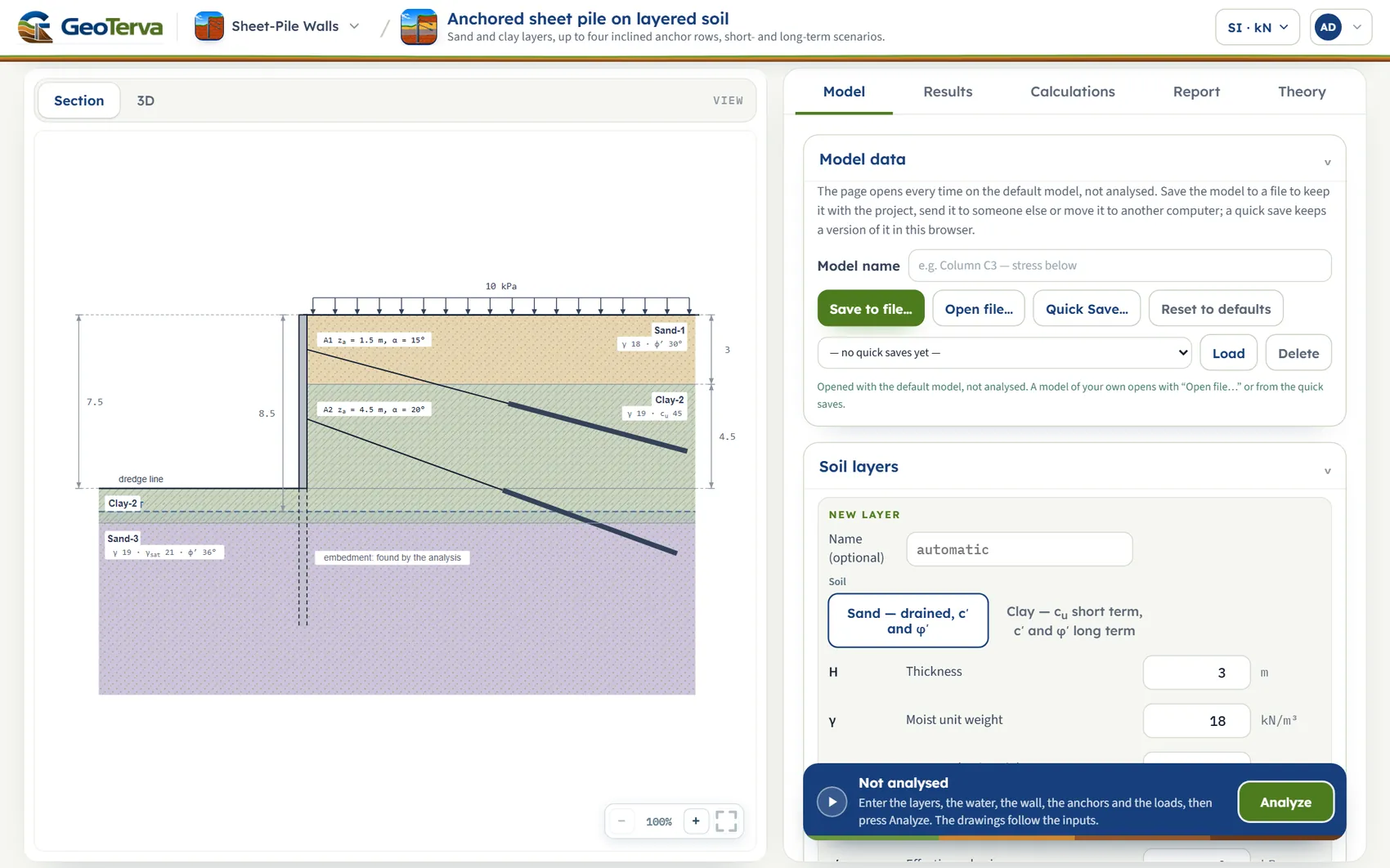
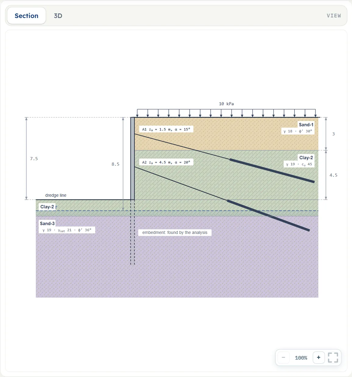
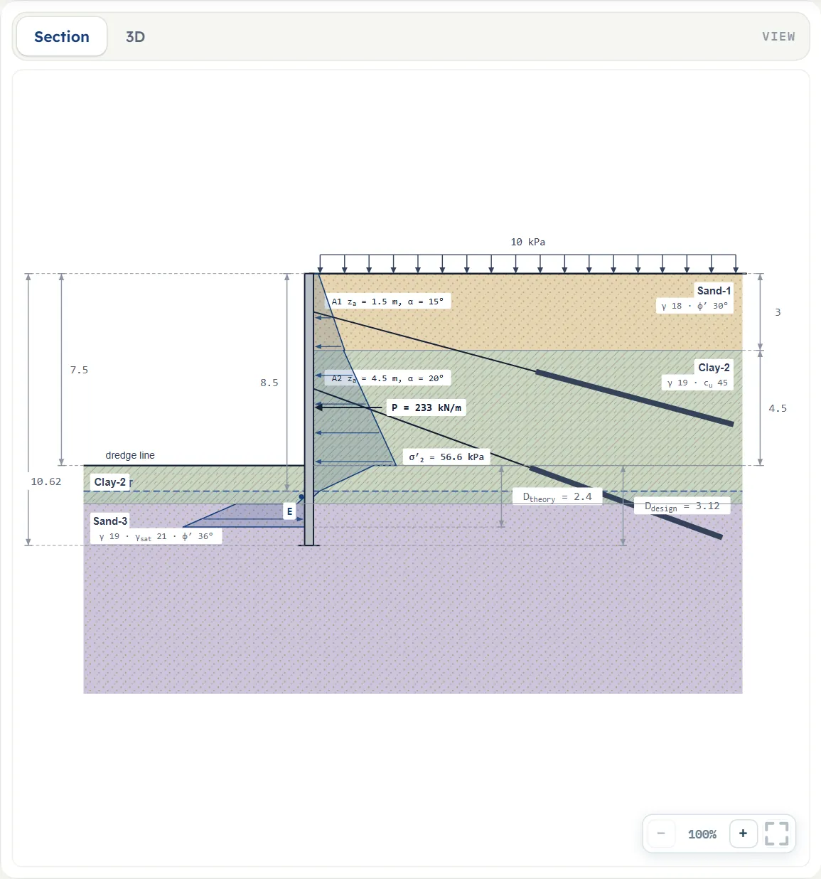
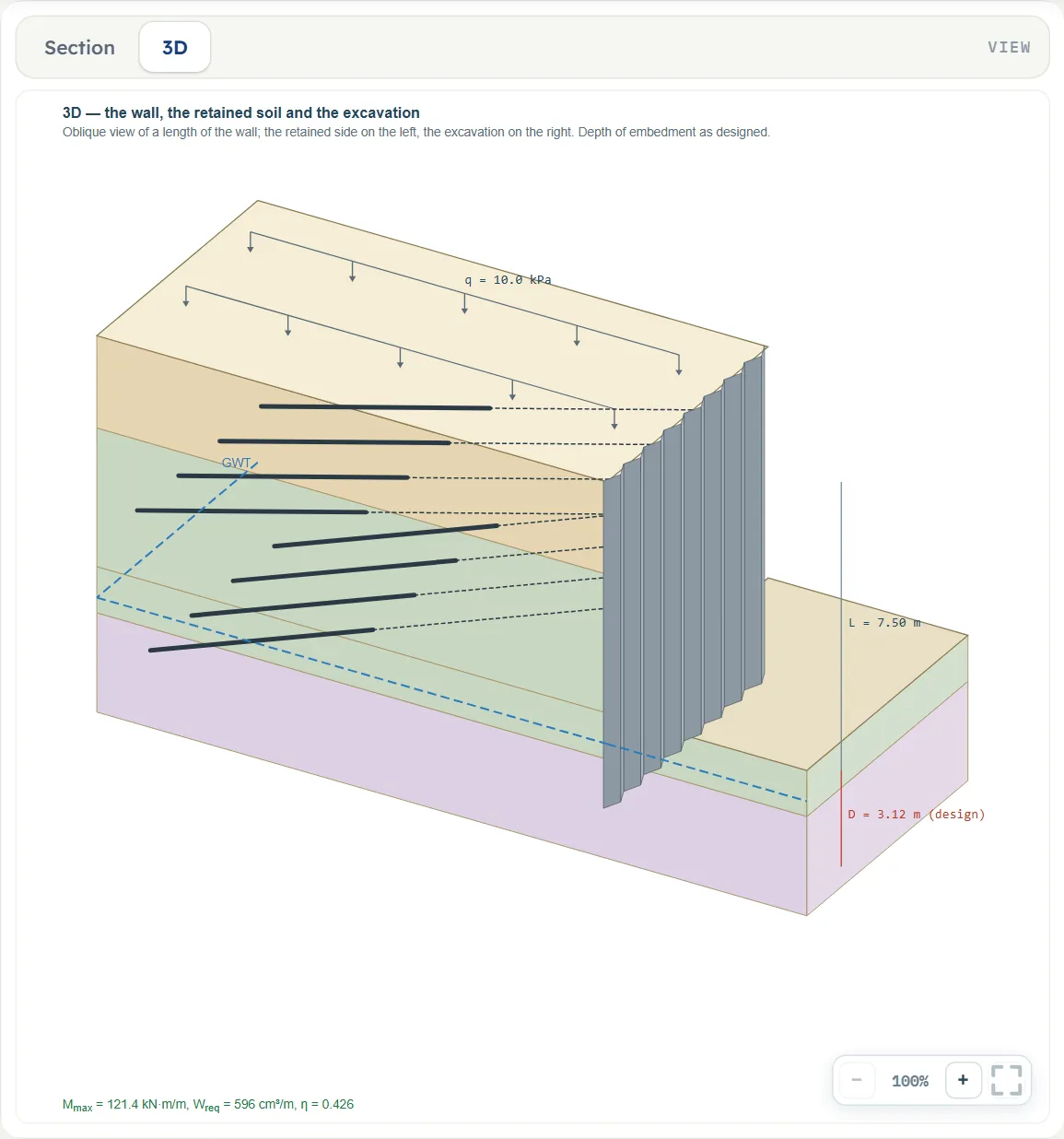
Zoom
Each view has −, a percentage and + at the lower right, and a button that fits the whole drawing in the pane. The mouse wheel zooms as well. The module has no Show chips: the drawings are fixed.
Dragging and picking on the drawing
Before Analyze, parts of the section drawing can be dragged and every row of a list can be picked:
- The water table Dw: drag its handle up or down; it moves in steps of 0.05 m and cannot go above the top of the wall (0 m). With Different level, the level in the excavation Dw,exc has a handle of its own.
- A layer boundary: drag it in steps of 0.05 m. Between two layers that both have a thickness, the layer above grows and the one below shrinks by the same amount; the boundary above the last layer changes only the layer above. A layer keeps at least 0.1 m.
- The toe of the wall: drag the toe handle; the embedment switches to Given — verify it and the depth follows the pointer (at least 0.1 m).
- Strip and point loads: drag a strip load by its body, its near edge or its far edge, and a point load by its mark, in steps of 0.05 m.
- Picking: press a layer, an anchor or a surcharge load on the drawing and its section opens with that row in the form (Editing · …); this is the same as pressing the row in the table.
The handles update the box of the same field, so you can see the value you drop. After Analyze the handles are gone and the inputs are locked: the bar says “The model is locked — its inputs, and Reset, Open and Load. Edit inputs clears the results; the unit system can still be changed.” Edit inputs unlocks the model, clears the results and takes the drawing back to the inputs.
Entering the model, section by section
The Model tab has eleven sections: Model data, Soil layers, Groundwater, Wall and embedment, Base heave, Ground anchor, Surcharge, Earthquake, Design factors, Sheet pile and Design code. Each opens when you click its title; Next and Back at the foot walk you through them, and Analyze waits below the last one. The tables list every field with its symbol, the unit in each unit system and its default. Where a unit is shown twice or three times, such as m · ft, the units are those of SI · kN, SI · tf and US in turn, and equal ones are merged. Defaults are shown in SI; in US the boxes show the converted values, for example 24.606 ft for the 7.5 m wall, and a unit switch may show them unrounded.
Model data
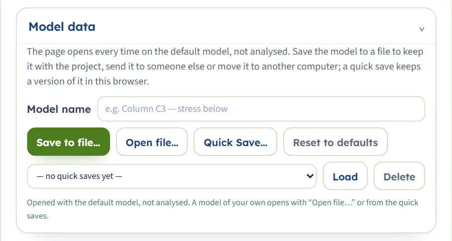
The first section holds the model name, Save to file…, Open file…, Quick Save… with its list and Load and Delete, and Reset to defaults. It works as described in the workspace guide. Reset returns the default model; after Analyze, Open, Load and Reset are locked until you press Edit inputs.
Soil layers
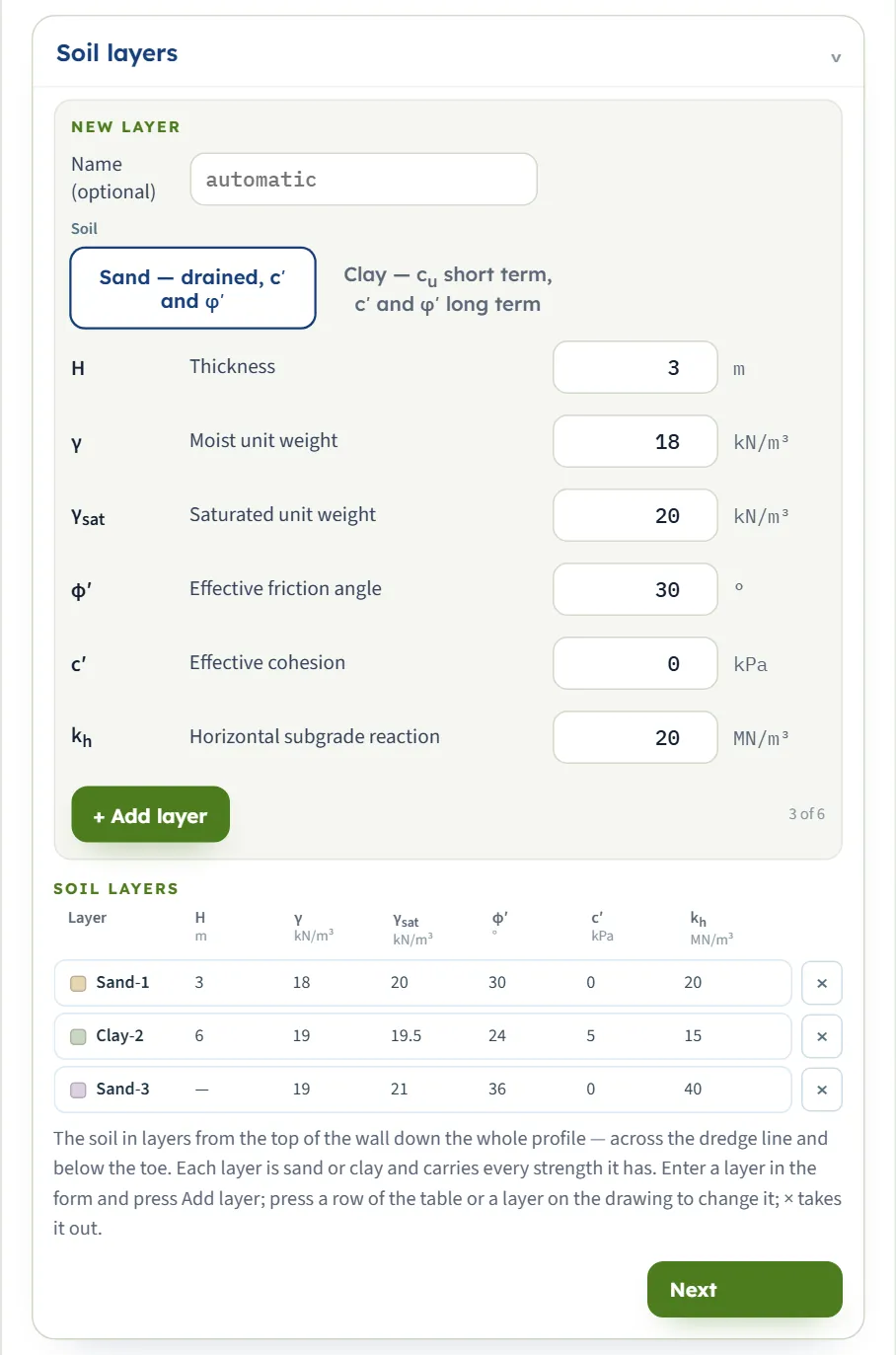
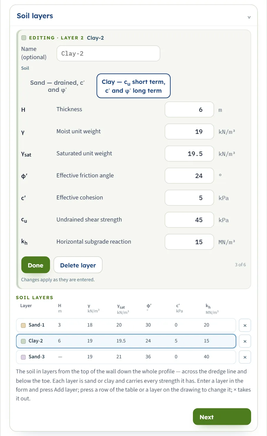
The section is a form over a table. The New layer form takes the name, the soil (Sand — drained, c′ and φ′ or Clay — cu short term, c′ and φ′ long term) and the values of one layer. + Add layer puts it at the bottom of the table, and a counter beside the button shows how many of the six layers there are. A clay adds the field cu to the form. The Soil layers table lists every layer with a swatch of its colour on the drawing. Press a row to change that layer in the form: the form then reads Editing · Layer 2 Clay-2, offers Done and Delete layer, and the note says that changes apply as they are entered. × takes a layer out.
A sand is always analysed drained, with c′ and φ′, in every scenario. A clay is analysed undrained in the short term and drained in the long term, so it needs all of cu, c′ and φ′. The same form values start the first layer and the New layer form (sand, 3 m, 18, 20, 30°, 0, 20 MN/m³; a clay form starts with cu = 40 kPa).
| Field | Default | What to enter |
|---|---|---|
| Name | automatic | Shown on the drawing and in the tables. Blank gives Sand-1, Clay-2 … by the soil and the position. (optional) |
| Soil | Sand | Sand (drained) or Clay (short term and long term), as on the two buttons. |
| Thickness Hi m · ft | 3 | From the top of the wall down. At least 0.1 m. The last layer has no thickness: its row shows a dash and it runs on below the toe. |
| Moist unit weight γ kN/m³ · t/m³ · pcf | 18 | At least 1. Used above the water table of each face. |
| Saturated unit weight γsat kN/m³ · t/m³ · pcf | 20 | At least 1. Used below the water table of each face. |
| Effective friction angle φ′ ° | 30 | From 0° to 50°, and above 0° for a layer that is analysed drained. A sand uses it always; a clay in the long term. |
| Effective cohesion c′ kPa · kg/cm² · psf | 0 | Zero or more. Zero for a clean sand. |
| Undrained shear strength cu kPa · kg/cm² · psf | 40 | At least 1. The short-term strength of the clay, with φ = 0. Also used by the heave check and by the clay in the earthquake. Shown when the soil of the layer is Clay. |
| Dry unit weight γd kN/m³ · t/m³ · pcf | 17 · 17 · 18 | At least 1. Only the dry mass of a sand carries inertia when the pore water is free in the earthquake. Layers 1 to 3 of the default model have 17, 17 and 18. Shown when the earthquake check is on, the pore water is Free and the soil is Sand. |
| Horizontal subgrade reaction kh MN/m³ · t/m³ · pci | 20 · 15 · 40 | Used only for the displacement: the stiffness of the soil on both faces of the wall. A model parameter rather than a soil constant. (optional) Leave it empty and the displacement is not computed. Layers 1 to 3 of the default model have 20, 15 and 40. |
Groundwater
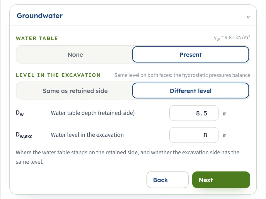
Water table has None and Present (the default); the unit weight of water γw = 9.81 kN/m³ is shown. With water present, Level in the excavation has Same as retained side (the hydrostatic pressures on the two faces balance) and Different level, which adds a second box. The module takes each face hydrostatic with its own level and no seepage; see Messages for the validity banner this puts on the results.
| Field | Default | What to enter |
|---|---|---|
| Water table depth (retained side) Dw m · ft | 8.5 | Measured down from the top of the wall, behind the wall. A depth below the toe has no effect on the wall. Shown when the water table is Present. |
| Water level in the excavation Dw,exc m · ft | 8 | Also measured down from the top of the wall. A depth smaller than L means water standing in the excavation above the dredge line. Shown when the level in the excavation is Different. |
Wall and embedment
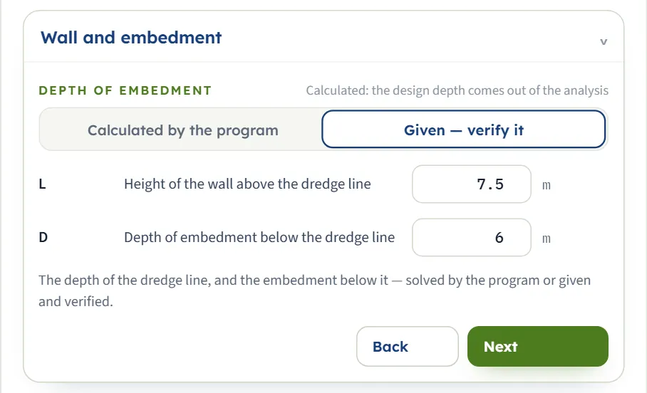
Depth of embedment has Calculated by the program (default) and Given — verify it. Calculated: the embedment comes out of the analysis. Given: you enter the depth of the toe below the dredge line; the module still solves the depth the design needs, compares the two with the utilisation URD = Dreq / Dgiven and finds the factor of safety the given depth mobilises on the passive pressure.
| Field | Default | What to enter |
|---|---|---|
| Height of the wall above the dredge line L m · ft | 7.5 | From the top of the wall to the dredge line. At least 0.5 m. The layers run on below it, and the part of the profile below the dredge line acts on both faces. |
| Depth of embedment below the dredge line D m · ft | 6 | At least 0.1 m. Shown when the embedment is Given. |
Base heave
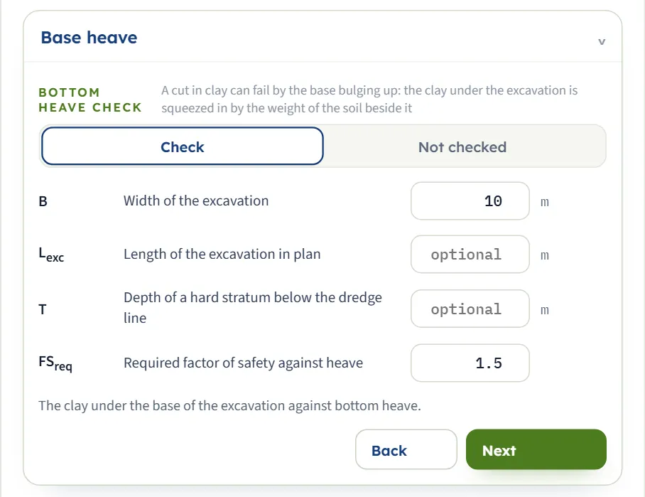
A cut in clay can fail by the base bulging up. Bottom heave check has Check (default) and Not checked. The check takes the clay under the dredge line; it does not apply to a base of sand, and the module says so (see Messages). The width B is needed, and the other three fields are optional or have defaults.
| Field | Default | What to enter |
|---|---|---|
| Width of the excavation B m · ft | 10 | The size of the failure surface follows from it. |
| Length of the excavation in plan Lexc m · ft | empty | Optional. Empty means a long excavation, with the shape term taken as 1. |
| Depth of a hard stratum below the dredge line T m · ft | empty | Optional. A hard stratum at 0 m means heave cannot develop. |
| Required factor of safety against heave FSreq | 1.5 | From 1 to 3. The result is PASS at or above it. |
Ground anchor
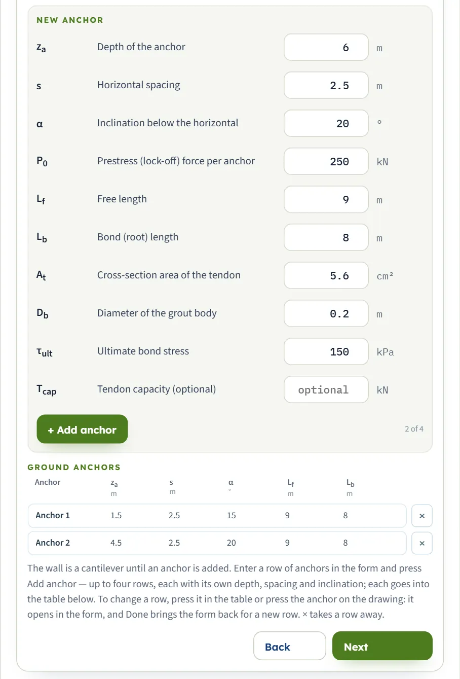
The wall is a cantilever until an anchor is added. The section holds the choices that apply to every row, a New anchor form and a table. Tendon is Strand (default) or Bar and sets the minimum free length. Critical surface for the free length is Automatic (one sand over the retained height) or Given — plane at an angle. + Add anchor puts the form into the table, up to four rows; press a row (or the anchor on the drawing) to edit it, Done returns the form for a new row, × takes a row away. The rows are taken in order of depth.
The two rows of the default model are at za = 1.5 m, α = 15° and za = 4.5 m, α = 20°; the form starts at za = 6 m, α = 20° (and a third and fourth row would default to 6 m and 7 m).
| Field | Default | What to enter |
|---|---|---|
| Required factor of safety of the bond FSreq | 2 | From 1 to 4. A default, not a code requirement. |
| Angle of the given surface from the horizontal θs ° | 60 | From 20° to 85°. Shown when the critical surface is Given. |
| Depth of the anchor za m · ft | 1.5 · 4.5 · 6 · 7 | Strictly between the top of the wall and the dredge line. |
| Horizontal spacing s m · ft | 2.5 | At least 0.5 m. Each anchor carries the reaction of its row over this spacing. |
| Inclination below the horizontal α ° | 15 · 20 | From 0° to 60°; beyond 45° the module cautions. |
| Prestress (lock-off) force per anchor P0 kN · tf · kip | 250 | Zero or more. |
| Free length Lf m · ft | 9 | At least 0.5 m. The unbonded length; it also sets the stiffness of the anchor in the displacement model. |
| Bond (root) length Lb m · ft | 8 | At least 0.5 m. |
| Cross-section area of the tendon At cm² · in² | 5.6 | Four 0.6 in strands are about 5.6 cm². |
| Diameter of the grout body Db m · ft | 0.2 | From 0.05 m to 1 m. The bonded diameter, not the tendon. |
| Ultimate bond stress τult kPa · t/m² · ksf | 150 | From your tests or tables; at least 1. |
| Tendon capacity Tcap kN · tf · kip | empty | Optional. Empty reports the force only. |
Surcharge
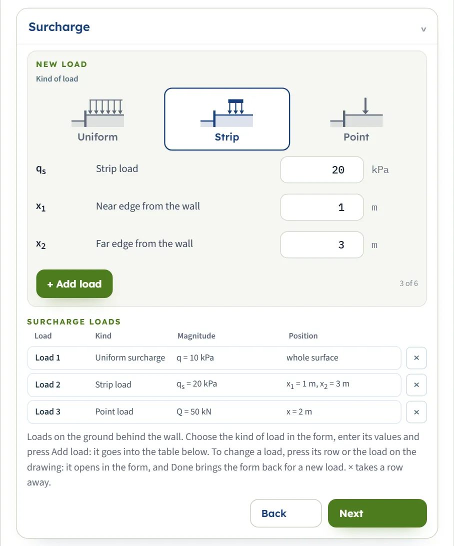
Loads on the ground behind the wall. In the New load form choose the kind of load, enter its values and press + Add load; up to six loads go into the table, which shows each kind, magnitude and position. The first load of the default model is a uniform surcharge of 10 kPa over the whole surface. Uniform loads add together; strip and point loads add their lateral pressure by the elastic solutions for a rigid wall.
| Field | Default | What to enter |
|---|---|---|
| Uniform surcharge on the retained surface q kPa · t/m² · ksf | 10 | Over the whole surface; adds to the vertical stress at every depth. Shown when the kind is Uniform. |
| Strip load qs kPa · t/m² · ksf | 20 | The pressure of the strip. Shown when the kind is Strip. |
| Near edge and far edge from the wall x1, x2 m · ft | 1 and 3 | The far edge is beyond the near edge. Shown when the kind is Strip. |
| Point load Q kN · tf · kip | 50 | A concentrated load. Shown when the kind is Point. |
| Distance from the wall x m · ft | 2 | A load closer than 0.30 m is taken at 0.30 m. Shown when the kind is Point. |
Earthquake
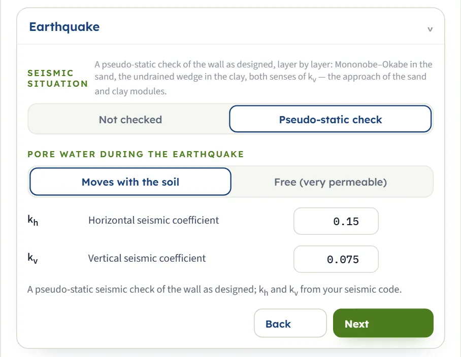
Seismic situation has Not checked (default) and Pseudo-static check. With the check on, Pore water during the earthquake asks whether the water Moves with the soil or is Free (very permeable), and the two coefficients appear. The module takes the wall as designed, layer by layer: Mononobe–Okabe in a sand and in a drained clay, a 45° wedge in an undrained clay, and both senses of kv.
| Field | Default | What to enter |
|---|---|---|
| Horizontal seismic coefficient kh | 0.15 | Up to 0.6; take it from your seismic code. Shown when the check is on. |
| Vertical seismic coefficient kv | 0.075 | From 0 to 0.4; take it from your seismic code. Shown when the check is on. |
Design factors
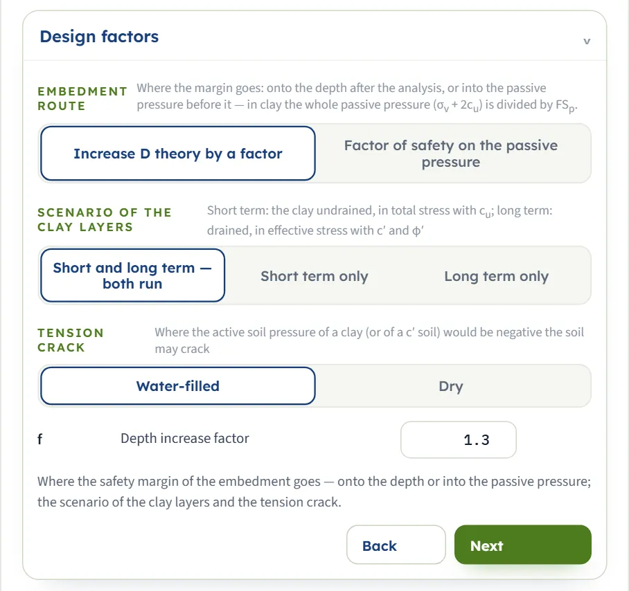
Three choices decide where the margin of safety goes and which analyses are run; they are explained in the next section.
| Field | Default | What to enter |
|---|---|---|
| Depth increase factor f | 1.3 | From 1 to 1.6. Dreq = f × Dtheory. Shown when the route is Increase D theory by a factor. |
| Factor of safety on the passive pressure FSp | 1.5 | From 1 to 3. The passive pressure is divided by it before the embedment is solved. Shown when the route is Factor of safety on the passive pressure. |
Sheet pile and design code
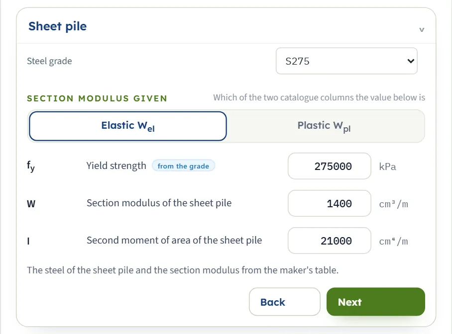
Steel grade is a list of S235, S275 (default), S355 and Typed; the yield strength fy follows the grade (the field shows “from the grade”) and is typed freely with Typed. The section is given by its modulus per metre of wall, and Section modulus given says whether that is the Elastic Wel (default) or the Plastic Wpl column of the maker’s table. I is the second moment of area, used only for the displacement.
| Field | Default | What to enter |
|---|---|---|
| Yield strength fy kPa · t/m² · ksf | 275000 (S275) | From the grade, or typed. |
| Section modulus of the sheet pile W cm³/m · in³/ft | 1400 | (optional) Empty gives Wreq only, with no section verified. |
| Second moment of area of the sheet pile I cm⁴/m · in⁴/ft | 21000 | (optional) Empty and the displacement is not computed. |
Design code has EN 1993-1-1 (Eurocode 3) (default) and AISC 360-22. With EN 1993-1-1 the earth-pressure moment is multiplied once by γF (default 1.35, from 1 to 1.6) and the resistance is Mc,Rd = W fy / γM0 (γM0 default 1, from 1 to 1.3). With AISC 360-22 you also choose LRFD (the moment factored by γH, default 1.6, from 1 to 2, against the design strength) or ASD. The embedment keeps the margin of its own route and is not factored again.
Choosing the method and the margin
Four decisions shape the answer beyond the soil and the loads.
| Choice and options | What it does |
|---|---|
| Embedment route Increase D theory by a factor, Factor of safety on the passive pressure | The margin goes onto the depth after the analysis, or into the passive pressure before it. With the example, the factor 1.3 gives Dreq = 3.124 m from Dtheory = 2.403 m; a factor of safety of 1.5 on the passive pressure gives 3.273 m. |
| Scenario of the clay layers Short and long term — both run, Short term only, Long term only | Both run by default, and the larger of each result designs the wall. With the example, the short term alone gives 2.014 m and the long term 3.124 m. |
| Tension crack Water-filled, Dry | Where the active pressure of a clay (or a c′ soil) would be negative, the soil is taken to crack: with water in the crack, its pressure γw(z − zt) acts on the wall. |
| Critical surface (anchored) Automatic (one sand over the retained height), Given — plane at an angle | The surface that the free length must clear. Automatic: a plane from the foot of the wall at the dredge line rising at 45° + φ′/2, available when a single sand layer makes up the retained height; otherwise enter the angle you have established. |
Depth factor or factor of safety on the passive pressure
With the depth factor route the diagram is solved with the full passive resistance and the depth found, Dtheory, is multiplied by f; the moment and the anchor forces are those of the diagram with the full passive pressure. With the factor of safety route the passive soil pressure (in a clay the whole of it, σv + 2cu) is divided by FSp before the depth is solved, so the moment and the anchor forces change too: in the example Mmax goes from 121.4 to 153.3 kN·m/m and T2 from 352.0 to 386.6 kN. The Calculations tab prints the other route’s depth as well. A factor of 1 (2.403 m in the example) removes the margin and the module notes it.
Short term and long term
When the profile has a clay, the module runs two analyses on the same profile: in the short term the clay is undrained (active σv − 2cu but never less than the pore water, passive σv + 2cu); in the long term every layer is drained. The anchor forces, the embedment and the moment are each the larger of the two. In the example the long term governs both the embedment (3.124 m against 2.014 m) and the moment (121.4 against 59.49 kN·m/m); that is why the tension crack choice makes no difference there, since the long-term profile has no negative active pressure (the dry crack run gives the same 3.124 m). A profile of sand alone has one analysis. The Calculations tab prints the scenarios side by side and says which one governs.
The anchored wall in the statics
- One row: free earth support. The anchor is a simple support, the toe is free, and the moment about the anchor gives the embedment.
- Several rows: the hinge method. A hinge at every anchor below the uppermost, simple spans between the anchors, and free earth support below the lowest one.
- No anchor: the conventional cantilever method with the toe block, where the pressure reverses below a point near the toe.
- The force of a row per metre of wall is F; the force in each anchor is T = F s / cos α along the tendon, and Tv = T sin α is its vertical part, reported for the vertical equilibrium of the wall.
- The smallest admissible embedment is the design. When there are several admissible roots, the module says so and takes the smallest.
Press Analyze and read the results
Press Analyze. The module checks the inputs first and shows Cannot analyse with each fault if there are any; otherwise it calculates, the bar reads Analysed — the sheet-pile wall calculated (with the number of warnings), the inputs lock, and a Warnings window opens if there is anything to report. The module stays on the Model tab; the answer is in the Results tab, and the drawing shows the pressure and the embedment. Before Analyze the Results tab reads “Press Analyze on the Model tab to calculate the sheet-pile wall.”
What the Results tab holds
- A bar of warnings with a Warnings (n) button.
- Three diagrams: the components of the lateral pressure on the two faces and the net pressure; the shear force and bending moment with the anchor forces as jumps of the shear and Mmax where the shear is zero; and the displacement and bending moment of the wall by the subgrade reaction method.
- Values, step by step: the headline value of every calculation step.
- Tables: the layers and their coefficients, the three stress fields, the components of the pressure at the events of the model, the roots of the moment equation, the resultants, the scenarios side by side and the anchors with their forces, free lengths and bond.
- The cards and the list of results, with a verdict where there is one.
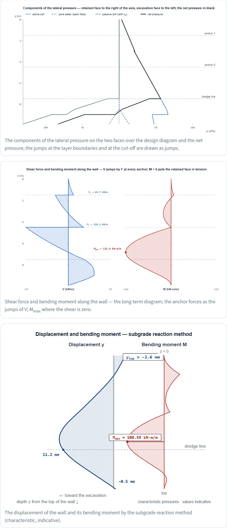
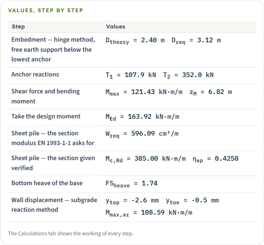
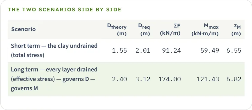
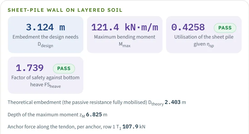
The cards and the list
| Result | Symbol | Meaning |
|---|---|---|
| Embedment the design needs | Ddesign | The depth of the toe below the dredge line: Dreq (the route’s margin included). With a given depth it reads Embedment of the wall as given, with a verdict. |
| Maximum bending moment | Mmax | Per metre of wall; with a given depth it is the larger of the design diagram and the given-depth equilibrium case and reads “designed for”. |
| Utilisation of the sheet pile given | ηsp | MEd / Mc,Rd (or Mu / φMn in AISC 360-22); PASS up to 1, and PASS · NEAR close to it. |
| Factor of safety against bottom heave | FSheave | Against the required value of the Base heave section. |
| Theoretical embedment | Dtheory | The depth with the full passive resistance. |
| Depth of the maximum moment | zM | Below the top of the wall, where the shear is zero. |
| Anchor force along the tendon, per anchor | T1, T2 … | One per row, from the larger scenario; with a given depth, “designed for” the larger of the two cases. |
| Free length required | Lf,req | Where the automatic or given critical surface is available. A free length shorter than this is a stop, so a result that is shown is always PASS. |
| Preliminary bond factor of safety | FSbond | Tult / max(T, P0) with Tult = π Db Lb τult; PASS at or above the required value. |
| Free length against the minimum | Lf | The free length you gave against the minimum for the tendon (4.5 m strand, 3 m bar). |
| Lock-off load against the bond capacity | ηlock | P0 / Tult, a check that the inputs of an anchor agree with each other; PASS up to 1. |
| Section modulus the sheet pile needs | Wreq | The number to look a sheet-pile table up with. |
| Top displacement of the wall | ytop | By the subgrade reaction method; indicative. |
The verdict words are those of the module: PASS, FAIL, PASS · NEAR, and PRELIMINARY (when the water stands at different levels, see Messages). The earthquake adds its own results (below).
Given depth
With Given — verify it, the module also gives Dreq, the utilisation URD = Dreq / Dgiven and the factor of safety FSp,mob the given depth mobilises on the passive pressure, and it works a second case with the wall in equilibrium at the given depth; the moment and the anchor forces are the larger of the two cases. In the example, a depth of 2.5 m gives URD = 1.250 (FAIL) and FSp,mob = 1.056; a depth of 4 m gives URD = 0.7810 (PASS) and FSp,mob = 1.907, but the maximum moment is then 180.0 kN·m/m against 121.4 with the depth calculated, because a longer wall in equilibrium with a partly mobilised passive resistance bends more, and T2 is 413.3 kN.
The earthquake
With the pseudo-static check on, the Results tab adds a fourth diagram, Seismic situation — net pressure and bending moment (with Mmax,E = 277.21 kN·m/m for the example), and the embedment required in the seismic situation DE, the maximum bending moment Mmax,E and the utilisation of the sheet pile ηE in the seismic situation, the seismic anchor force TE of each row and the preliminary bond factor of safety FSbond,E, which is held to the required factor divided by 1.33. With the default coefficients (0.15 and 0.075, pore water moving with the soil) the example gives DE = 4.348 m (FAIL, since it is more than the design embedment 3.124 m), Mmax,E = 277.2 kN·m/m, ηE = 0.7200 (PASS), TE,1 = 213.3 kN, TE,2 = 623.3 kN and FSbond,E of row 2 = 1.210 (FAIL). With the pore water free it gives DE = 4.089 m, Mmax,E = 266.5 kN·m/m and ηE = 0.6922 (PASS).
The Calculations tab, the report and the Theory tab
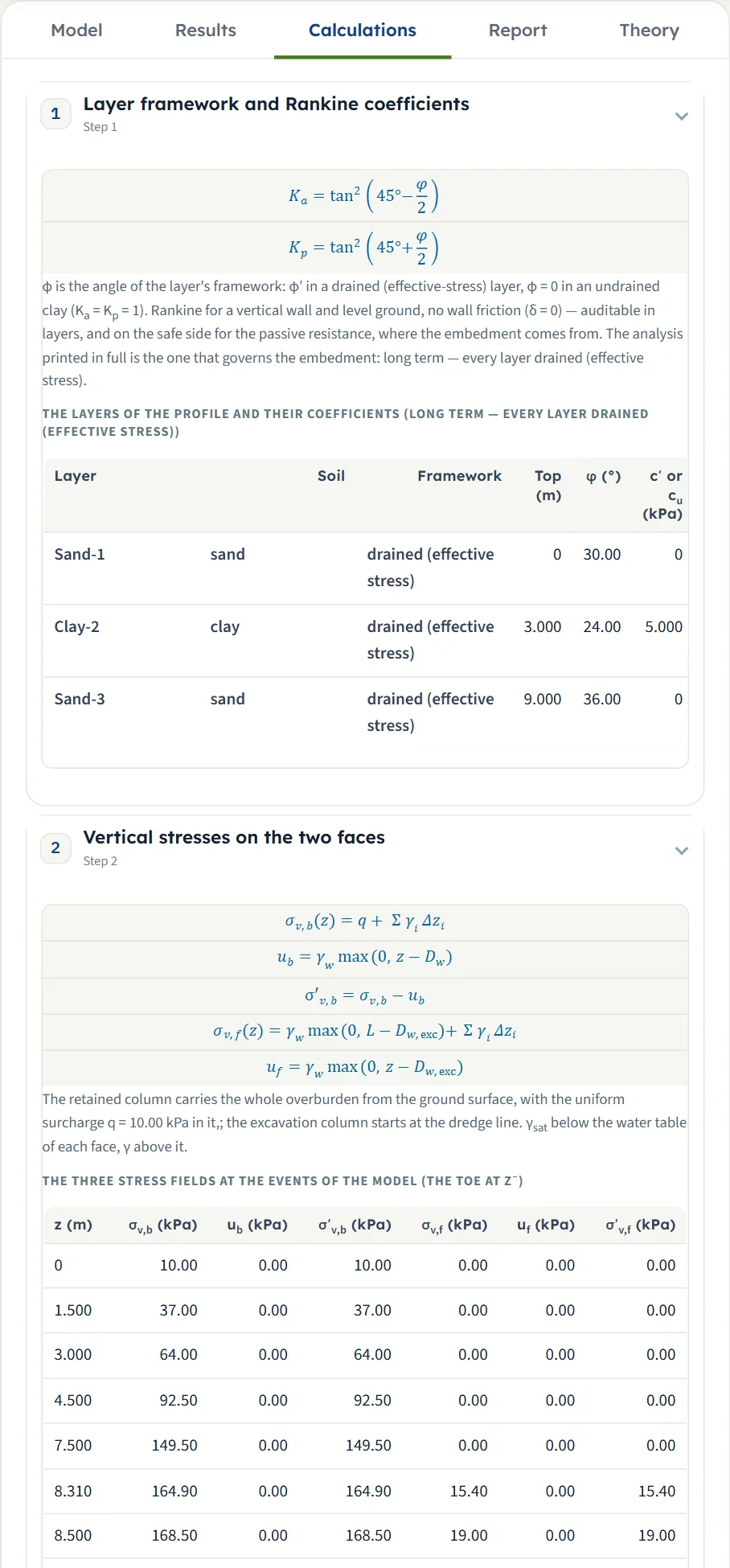
The Calculations tab writes the working with your numbers, one step at a time, each with its equations. For the default model there are fourteen steps: Layer framework and Rankine coefficients, Vertical stresses on the two faces, Lateral pressures by layer framework, Tension cut-off and the crack (when a tension zone arises), Embedment — hinge method, free earth support below the lowest anchor, Anchor reactions, Shear force and bending moment, Short-term and long-term scenarios, Ground anchors — free length and preliminary bond, Take the design moment, Sheet pile — the section modulus … asks for, Sheet pile — the section given verified, Bottom heave of the base and Wall displacement — subgrade reaction method. A cantilever has the conventional-method step in place of the hinge steps; a given depth, the earthquake and the displacement add their own. The scenario that governs the embedment is the one printed in full.
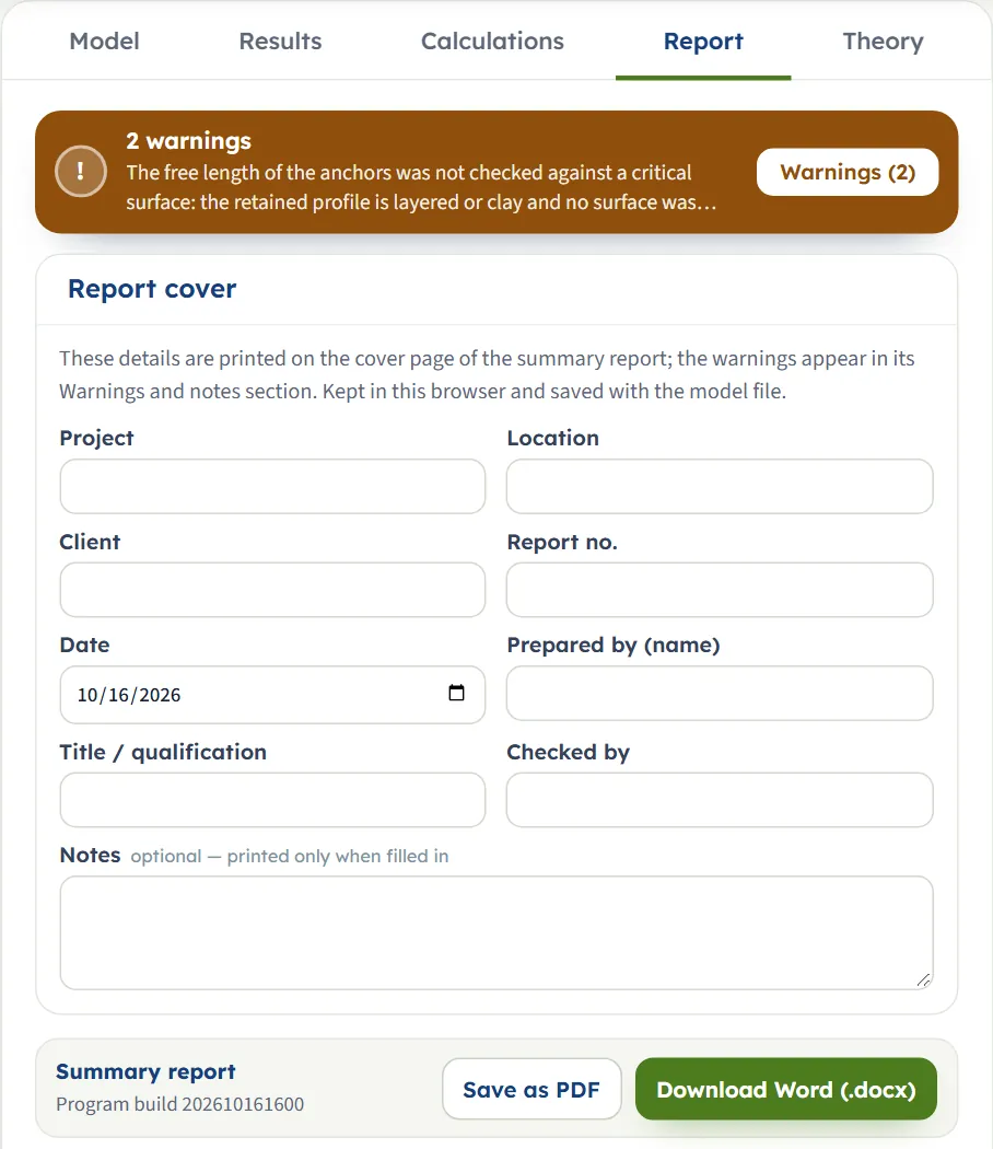
The Report tab has a Report cover (project, location, client, report number, date, prepared by, title, checked by and optional notes, kept in the browser and with the model file) and a preview of the summary report with Save as PDF and Download Word (.docx). The report has seven parts: Introduction and scope, Input data, Calculation, Results, Assumptions and notes, Summary and References, with a panel What passes and what does not that lists every check with the number it turned on and its verdict. The rows for the stability of the anchored block and of the whole excavation carry the word NOT CHECKED: they are reminders that those checks are made separately.
The Theory tab is a reading page with a contents list, Open all and Close all, and 21 sections, from Sheet-pile walls on layered soil (what the wall does and what the module designs): the wall and how it is held; the stresses on the two faces; the earth pressure in a drained layer and in an undrained clay; short and long term; surcharges; the net pressure diagram; where the margin of safety goes; the cantilever and its toe block; one row of anchors; several rows; shear force and bending moment; the anchors; the seismic situation; verifying the sheet pile; bottom heave; the displacement; the opening model worked through; what the module assumes; and the references.
Worked example: the default model
The default model is a 7.5 m wall in a profile of Sand-1 (3 m, γ = 18 kN/m³, φ′ = 30°), Clay-2 (6 m, γ = 19, γsat = 19.5 kN/m³, φ′ = 24°, c′ = 5 kPa, cu = 45 kPa) and Sand-3 (γ = 19, γsat = 21, φ′ = 36°); water at 8.5 m on both faces; a 10 kPa surcharge; anchors at 1.5 m (15°) and 4.5 m (20°), spacing 2.5 m, P0 = 250 kN, Lf = 9 m, Lb = 8 m, Db = 0.2 m, τult = 150 kPa; both scenarios, the depth factor 1.3; a sheet pile of 1400 cm³/m in S275, EN 1993-1-1.
What the module gives
| Result | Value | Where |
|---|---|---|
| Embedment | Dtheory = 2.403 m, Dreq = 1.3 × 2.403 = 3.124 m | Governed by the long term |
| Anchor forces per metre | F1 = 41.69, F2 = 132.32 kN/m | Calculations, step 6 |
| Anchor forces | T1 = 107.9 kN, T2 = 352.0 kN | Results, cards |
| Maximum moment | Mmax = 121.4 kN·m/m at zM = 6.825 m | Long term governs |
| Sheet pile | MEd = 1.35 × 121.4 = 163.92; Wreq = 596.1 cm³/m; Mc,Rd = 385.00; ηsp = 0.4258 (PASS) | Calculations, steps 10–12 |
| Bottom heave | FSheave = 1.739 (PASS, 1.5 required) | Calculations, step 13 |
| Bond | FSbond = 3.016 and 2.142 (PASS) | Results, list |
The module also warns that the free length was not checked against a critical surface (the retained profile is layered, so no automatic surface applies), and gives notes for the tension cut-off, the scenarios and the moment factor.
Checking it by hand
The net pressure is the active pressure of the retained side, pa = Ka σ′v − 2c′√Ka plus the water, less the passive pressure of the excavation side, pp = Kp σ′v + 2c′√Kp plus the water, with Ka = 0.3333, 0.4217, 0.2596 and Kp = 3.000, 2.371, 3.852 in the three layers (the Calculations tab prints them). An independent integration of this net pressure with the hinge method gives the same results:
| Quantity | Hand check | Module |
|---|---|---|
| Dtheory (the moment about anchor 2 vanishes) | 2.403 m | 2.403 m |
| F1 and F2 | 41.69 and 132.31 kN/m | 41.69 and 132.32 kN/m |
| T1 = 41.69 × 2.5 / cos 15° | 107.9 kN | 107.9 kN |
| T2 = 132.31 × 2.5 / cos 20° | 352.0 kN | 352.0 kN |
| Mmax | 121.4 kN·m/m at 6.82 m (a finer sum) | 121.4 kN·m/m at 6.825 m |
| Tult = π × 0.2 × 8 × 150; FSbond | 754.0 kN; 754.0/250 = 3.016 and 754.0/352.0 = 2.142 | 3.016 and 2.142 |
| Wreq = 163.92 / 275 000 | 596.1 cm³/m | 596.1 cm³/m |
| Mc,Rd = 1400 cm³/m × 275 MPa; ηsp | 385.0 kN·m/m; 163.92/385.0 = 0.4258 | 385.00; 0.4258 |
| FSheave = (5.14 × 45 + 27 × 7.5/7.07) / (149.5) | 259.9 / 149.5 = 1.74 | 1.739 |
The free length required of an automatic surface can be checked the same way. With one sand layer over the retained height (Sand-1 made 9 m thick, φ′ = 30°), the plane rises at 45° + 15° = 60° from the foot of the wall: sc = (7.5 − 1.5) / (cos 15° tan 60° + sin 15°) = 3.106 m, and Lf,req = 3.106 + max(1.5 m, 7.5/5 m) = 4.606 m; the module gives 4.606 m for row 1 and 3.023 m for row 2 (hand: 3.023 m).
The same model in US units and in SI · tf
Switch the unit system in the header: the model is the same. In US the module gives Ddesign = 10.25 ft (Dtheory = 7.884 ft), Mmax = 27.30 kip·ft/ft at zM = 22.39 ft, T1 = 24.26 kip, T2 = 79.14 kip and Wreq = 11.09 in³/ft; the ratios (ηsp 0.4258, FSheave 1.739) are unchanged. In SI · tf it gives Ddesign = 3.124 m, Mmax = 12.38 tf·m/m, T1 = 11.00 tf and T2 = 35.90 tf. These agree with the kN results: 107.9 kN = 24.26 kip = 11.00 tf, and 121.43 kN·m/m = 27.30 kip·ft/ft = 12.38 tf·m/m.
How each input changes the answer
Every row is a run of the module that changes one input of the default model (the soil, water, anchors, loads and the 1.3 depth factor of the example above) and leaves the rest. D is the embedment the design needs (m), M the maximum moment (kN·m/m) and T₁ / T₂ the anchor forces (kN) of rows 1 and 2.
| Change | D | M | T₁ / T₂ |
|---|---|---|---|
| Default model | 3.124 | 121.4 | 107.9 / 352.0 |
| Wall height 9 m Row 2 bond fails (FS 1.496); the sheet pile of the example is over-used | 4.373 | 291.5 | 107.9 / 504.0 |
| Wall height 6 m | 2.435 | 31.24 | 107.9 / 219.4 |
| Surcharge 30 kPa Bottom heave drops to 1.534 | 3.433 | 152.2 | 167.8 / 438.4 |
| No surcharge | 2.965 | 106.9 | 77.92 / 309.7 |
| Water table at 3 m (both faces) | 3.169 | 86.44 | 106.0 / 274.6 |
| No water | 2.825 | 117.3 | 107.9 / 347.3 |
| Water in the excavation at 7 m, retained side 8.5 m Results carry PRELIMINARY in place of PASS | 3.510 | 127.6 | 107.9 / 359.0 |
| Clay cu 25 kPa (from 45) Bottom heave 0.9660 (FAIL); row 2 bond fails | 3.946 | 237.6 | 107.9 / 548.0 |
| Clay cu 90 kPa Only the heave changes, to 3.477 | 3.124 | 121.4 | 107.9 / 352.0 |
| Clay c′ 0 (from 5 kPa) | 3.523 | 162.6 | 114.2 / 437.7 |
| Clay φ′ 18° (from 24°) | 3.633 | 180.7 | 114.7 / 474.6 |
| Last sand φ′ 32° (from 36°) | 3.574 | 127.4 | 107.9 / 358.8 |
| Last sand φ′ 40° | 2.834 | 117.7 | 107.9 / 347.8 |
| First sand γ 20 (from 18) | 3.218 | 130.4 | 116.8 / 379.0 |
| Depth factor 1.0 (from 1.3) No margin on the depth | 2.403 | 121.4 | 107.9 / 352.0 |
| Depth factor 1.6 The upper limit; only the depth changes | 3.845 | 121.4 | 107.9 / 352.0 |
| Factor of safety 1.5 on the passive pressure | 3.273 | 153.3 | 107.9 / 386.6 |
| Short term only | 2.014 | 59.49 | 88.78 / 151.5 |
| Anchor 1 inclination 30° (from 15°) Only T1 changes: 41.69 × 2.5 / cos 30° | 3.124 | 121.4 | 120.3 / 352.0 |
| Spacing 4 m (both rows) Row 2 bond fails | 3.124 | 121.4 | 172.6 / 563.2 |
| Anchor 2 at 6 m (from 4.5 m) | 2.641 | 65.71 | 161.8 / 371.5 |
| Anchor 2 removed (one row) Sheet pile of the example fails | 3.765 | 295.9 | 331.7 / — |
| A third row at 6 m Rows at 1.5, 4.5 and 6 m: T₃ = 260.7 | 2.641 | 47.39 | 107.9 / 166.2 |
| No anchors (cantilever) The sheet pile of the example fails (η 4.243) and the displacement is large | 10.44 | 1,210 | — / — |
Reading the table:
- A taller wall or a heavier load raises the embedment, the moment and the anchor forces together, and the bond of the lower row is the first check to fail.
- The strength of the clay moves the short term and the heave check strongly, but the design stays with the long term while it governs; a weaker cu reaches the design when the short term takes over (3.946 m).
- Water at 3 m instead of 8.5 m raises Ddesign only slightly (3.169 m) while it lowers Mmax (86.44) and T2 (274.6); with no water the embedment is 2.825 m. Try the water table of your site rather than guessing its effect.
- The factor of the depth route changes only the depth; the factor of safety on the passive pressure changes the whole diagram.
- The lowest row sets the embedment: a lowest row at 6 m gives Dreq = 2.641 m with two rows and 2.641 m with three; the third row at 6 m also lowers Mmax from 121.4 to 47.39 kN·m/m.
Messages
Messages come in four levels. Stops (a red ■ in the Cannot analyse window) mean that nothing was calculated; fix the field named. Cautions (△) are calculated results that need your attention. Notes (○) and information (●) state an assumption or a fact about the run. They appear in the Warnings window, in the bar and list of the Results tab, and in the report. Quotations below are the module’s text, with the numbers of the run that triggered them.
Input errors
- Cannot analyse — 1 input error: “Thickness (H1) must be at least 0.1 m.” The same form for “Effective friction angle (φ′1) must be at most 50°.”, “Height of the wall above the dredge line (L) must be at least 0.5 m.”, “Inclination below the horizontal (α) must be at most 60°.”, “Depth increase factor (f) must be at least 1.”, “Horizontal seismic coefficient (kh) must be at most 0.6.”, “Diameter of the grout body (Db) must be at most 1 m.”, “Required factor of safety of the bond (FSreq) must be at most 4.”, “Depth of embedment below the dredge line (D) must be at least 0.1 m.” The fields are marked in red.
- “Width of the excavation (B) is missing.”, “Water table depth (retained side) (Dw) is missing.”, “Water level in the excavation (Dw,exc) is missing.” and “Undrained shear strength (cu,2) is missing.” for a clay layer without cu.
Stops from the analysis
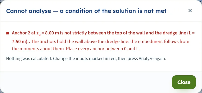
- “Anchor 2 at za = 8.00 m is not strictly between the top of the wall and the dredge line (L = 7.50 m).” Place every anchor between 0 and L.
- “Anchors 1 and 2 are less than 0.25 m apart (za = 1.50 m and 1.60 m).” Merge the two rows or move one.
- “Sand-1 has no effective friction angle φ′, which the drained analysis needs.” (and the same for the long term). A drained layer needs φ′ above 0.
- “No embedment up to Dmax = 30.00 m balances the wall.” The passive resistance never catches up with the retained pressure; raise the passive resistance, lower the water in the excavation, or add an anchor. The pressure diagram is drawn so that the cause can be seen.
- “The embedment roots found (short term) leave the anchor in compression.” The anchor is too low, or not needed: raise it or remove it (a single anchor at 7.4 m triggers it in the example).
- “Anchor 1 has a free length of 3.00 m, shorter than the 4.61 m that puts its bond zone behind the critical surface.” With a given plane at 60°. Lengthen the free length to at least Lf,req, or flatten the anchor. The same stop arises with the automatic surface when one sand makes up the retained height.
Cautions
- Free length of the anchors not checked against a critical surface — shown in the default model: the retained profile is layered or clay, so no automatic plane applies. Enter the plane you have established (Given — plane at an angle) or verify the position of the bond zones separately.
- Deep-seated stability of the block between the wall and the anchors — shown in every anchored run; it is verified separately.
- “Anchor 2: the preliminary bond capacity Tult = 754.0 kN gives FSbond = 1.50 < 2.00 against max(T, P0) = 504.0 kN, the anchor force.” Lengthen the bond length, enlarge the grout body, or reduce the spacing. When the lock-off load is the larger, the message says “the lock-off load”.
- “Anchor 2: the lock-off force P0 = 250.0 kN exceeds the entered preliminary ultimate bond capacity Tult = π Db Lb τult = 188.5 kN.” The inputs of the anchor do not agree.
- “Anchor 2: T = 352.0 kN exceeds the tendon capacity 300.0 kN.”
- “Anchor 1 is inclined at α = 50.00 °, outside the usual range 0–45°.”
- “Anchor 1 has a free length of 3.00 m, less than the 4.50 m … asks for a strand tendon.” A short free length also makes the displacement “based on invalid anchor geometry” (a note).
- “The sheet pile given does not carry the design moment: MEd / Mc,Rd = 1.49.” Take a heavier sheet pile or a higher grade.
- “The embedment given, D = 2.50 m, is less than the embedment the design needs, Dreq = 3.12 m (URD = 1.250).”
- “Factor of safety against bottom heave FS = 0.9660 is below the required 1.50.”
- “A dry tension crack was chosen: drainage condition must justify a dry tension crack.”
- “Strip load 2 starts at the wall (x1 = 0.00 m)” — the elastic solution is singular at the wall; keep the near edge clear if the layout allows.
- “Large displacement: ytop = 1,849.3 mm, 24.7 % of the retained height.” The beam on springs is a small-displacement idealisation.
- Anchor goes slack in the displacement model — a tendon takes tension only.
- Earthquake: “A saturated sand lies within the wall in the seismic situation: screen it for liquefaction.”; “The design embedment is too short for the seismic situation: DE = 4.35 m > Ddesign = 3.12 m.”; the seismic bond, tendon and section cautions; and “SEISMIC METHOD DOMAIN EXCEEDED” when θ ≥ φ′ (kh = 0.3, kv = 0.15 in the example), where the Mononobe–Okabe coefficient has no real solution.
- “DESIGN VALIDITY: PRELIMINARY — SEEPAGE EFFECT NOT INCLUDED.” With Different level water the pressures are hydrostatic on each face with no seepage: every PASS is shown as PRELIMINARY, and a second caution names the piping and base-heave check of the unequal heads as yours to make.
Notes and information
- “The overall stability of the wall and the ground has not been evaluated.” — shown in every run, a cantilever too: verify it separately, with a slope-stability analysis of the excavation.
- “The active soil pressure is clipped at zero over 3.00 m–4.37 m; the crack is taken water-filled.” with the result of the other crack assumption (“With the crack dry the design gives Dreq = 3.12 m …”).
- “Short- and long-term scenarios both run: Dreq 2.01 m / 3.12 m, Mmax 59.49 kN·m/m / 121.43 kN·m/m (short / long); the larger of each designs the wall.”
- “No passive-pressure reduction applied and no depth factor: Dreq = Dtheory …” (factor 1).
- “The base of the excavation was not checked against bottom heave”, “A hard stratum at the base — bottom heave cannot develop” and “Bottom heave — not applicable: the soil immediately beneath the base of the excavation, Sand-3 (sand, from 9.00 m), is not an undrained clay.”
- “No section modulus was given for the sheet pile: the modulus it needs is found, and no section is verified.” and “No second moment of area was given for the sheet pile: the displacement of the wall is not computed.”
- “The sheet pile is taken as of class 1 or 2 — the section class is not verified.” with the plastic modulus; the modulus is taken for the whole wall.
- “Point load 2 at x = 0.10 m is taken at 0.30 m from the wall.” and the information that a point load is taken at its most loaded section for the whole wall.
- Given depth: “The depth of embedment has been given and verified …”; and, when the lowest anchor takes no tension in the given-depth case, a note that it adds nothing to the design actions.
Good practice
- Check the profile before the numbers. The drawing follows your inputs: the layer colours, the dredge line, the water table and the anchors should look like your section before you press Analyze.
- Keep both scenarios for a clay. The long term governed the example, but a weaker cu (25 kPa instead of 45) makes the short term govern; the module cannot know which in advance, so leave Short and long term — both run.
- Keep the water-filled crack unless the site drains the crack; the module cautions on a dry crack and prints the water-filled result.
- Give a bond stress with a source. τult drives the bond check; the module treats it as the engineer’s number and the factor of 2 as a default.
- Use a surface you have established for the free length when the retained profile is layered; the automatic plane is for one sand over the whole retained height.
- Read the given-depth case as two cases. The moment and anchor forces are the larger of the design diagram and the equilibrium at your depth.
- Treat PRELIMINARY as preliminary. With different water levels the result carries no PASS; do the seepage and piping checks.
- Use the displacement as an indication. It depends directly on kh and on the second moment of area you give; the limit-equilibrium design does not depend on it.
- Save the model to a file before you close the page; the module opens on the default model every time.
- Put your own checks beside the result: the overall stability of the excavation, the deep-seated stability of the anchored block, the anchor tests, and the section classification of the sheet pile.
Frequently asked questions
What is the difference between this module and Sheet pile in sand or in clay?
Those two take a single kind of soil. This module takes a profile of up to six layers, each sand or clay, up to four rows of anchors, the scenarios of a clay side by side, and water at its own level on each face. See Sheet pile in sand and Sheet pile in clay.
Do I have to enter both short-term and long-term strength for a clay?
Yes. Every clay layer needs cu, c′ and φ′ whichever scenario you run; Short term only and Long term only in Design factors just run one analysis on them. A missing value stops the analysis with a message naming the layer, for example “Effective friction angle (φ′2) is missing.”
Why does the embedment come out larger than the one from the theory?
Because of the margin. Dreq is Dtheory multiplied by the depth factor (1.3 by default), or the depth found with the passive pressure divided by a factor of safety. Both depths are printed in the Calculations tab.
Which scenario governs, short term or long term?
The Calculations tab prints both side by side and marks the one that governs the embedment and the one that governs the moment. In the example the long term governs both; the module takes the larger of each quantity anyway, row by row for the anchors.
How many rows of anchors can I use, and how does the module treat them?
None to four. One row is free earth support; two to four rows use the hinge method, with a hinge at every anchor below the uppermost. Anchors must lie strictly between the top of the wall and the dredge line and at least 0.25 m apart.
Why does the module say the free length was not checked against a critical surface?
The automatic plane (45° + φ′/2 from the foot of the wall at the dredge line) applies when one sand layer makes up the whole retained height. For a layered or clay retained profile, choose Given — plane at an angle and enter the angle you have established; the module then tests every anchor against it.
What does PRELIMINARY mean in place of PASS?
It appears when the water stands at different levels on the two faces. The module takes each face hydrostatic with no seepage, so it issues no PASS; the pressures are valid within that model, and the seepage and piping checks are yours.
Can I give the depth of embedment myself?
Yes: choose Given — verify it in Wall and embedment. The module still solves the depth the design needs, gives URD and the factor of safety the given depth mobilises on the passive pressure, and designs the moment and the anchors for the larger of the design case and the given-depth case.
Why is the moment larger when I give a longer embedment?
A longer wall in equilibrium with a partly mobilised passive resistance can bend more than the design diagram. The module works that case and keeps the larger moment and anchor forces. In the example a given depth of 4 m raises Mmax from 121.4 to 180.0 kN·m/m.
Does the module keep my model when I reload the page?
No. It opens on the default model every time. Use Save to file… and Open file…, or Quick Save…, to keep a model; the report cover details are kept in the browser and with the model file.
Can I change the units after Analyze?
Yes. The module says that the unit system can still be changed while the model is locked; the inputs lock until you press Edit inputs, which also clears the results.
Which codes does the sheet pile check use?
EN 1993-1-1 (with γF on the moment and γM0 on the resistance) or AISC 360-22 (LRFD with γH, or ASD). The check uses the section modulus per metre you give, as the modulus of the whole wall, with the elastic or the plastic column of the maker’s table.