

What the module calculates
Pile in sand gives the ultimate axial capacity Qu and the allowable axial capacity Qall of one pile that is pushed, driven or bored into sand. The ultimate capacity is the sum of what the tip carries and what the shaft carries:
Qp is the point bearing, the resistance of the sand under the tip; Qs is the skin friction, the resistance along the shaft, worked out layer by layer; FS is the factor of safety. You choose the method for the point and the method for the shaft independently, and can put one factor of safety on the sum or one on each part.
What you can describe
- A ground of up to eight sand layers, each with its own thickness, unit weights and friction angle φ′, and an optional water table.
- A circular or square pile, driven, bored or jacked, of width or diameter D (at least 0.05 m) and embedded length L (at least 0.5 m).
- Three point-bearing methods: Meyerhof (1976), Vesic (1977) and Coyle & Castello (1981).
- Two skin-friction methods: the K–δ method and Coyle & Castello (1981), both applied to each layer separately.
What belongs to other modules
- This module treats one pile under an axial compression load. Neighbouring piles are covered by the Pile group module, and a sideways load by Pile under lateral load.
- The results are the resistance of the ground: the weight of the pile is not deducted, as the module says under its results.
- The layers here are sand. For clay, or for a profile that mixes sand and clay, use Pile in clay or Pile on layered soil.
Before you start: what you need
Have these ready from your ground investigation and your design:
| What | Where it comes from | Notes |
|---|---|---|
| The sand profile: layer thicknesses | Boring logs | The layers must reach at least the pile tip. Describing the sand about two pile widths below the tip is better: the point resistance is governed by the soil at and just below the tip. |
| Unit weights γ and γsat | Laboratory or correlations | γ applies above the water table, γsat below it. |
| Friction angle φ′ of each layer | SPT or CPT correlations, tests | An effective (drained) friction angle. The point-bearing chart of Meyerhof is drawn from 20° to 45°. |
| Water table depth | Piezometers, borings | Optional. Enter it only if it lies within the pile length. |
| Pile: shape, width or diameter, embedded length, installation | Your design | Installation decides which methods are open and what the module fills in for the shaft. |
| Factor of safety; applied working load | Your design basis | The module’s hint for the factor is 2.5 to 4. The applied load is optional. |
Quick start in eight steps
- Open the module and choose the units
Open Pile in sand from the Piles family. Pick SI · kN, SI · tf or US in the header; you can change it at any time. Open Pile in sand.
- Describe the sand layers
In Sand layers, fill in the New layer form (thickness, γ, γsat, φ′) and press + Add layer; the module already holds Sand-1 (25 m): click its row to edit it, then add the layers below it, from the ground surface down. Click a row to edit a layer, the cross to remove it. The layers must reach the pile tip.
- Set the groundwater
In Groundwater, choose Present and give the depth of the water table, or leave it at None.
- Describe the pile
In Pile, choose the shape (Circular or Square) and the installation (Driven, Bored or Jacked), then enter the width or diameter D and the embedded length L.
- Choose the method for the point
In Point bearing, pick Meyerhof, Vesic (it asks for m = Es/pa) or Coyle & Castello (it fills in N*q from the chart).
- Choose the method for the shaft
In Skin friction, pick the K–δ method or Coyle & Castello. Each layer has its own coefficient and, for the K–δ method, its own δ′; they are filled in and can be typed over.
- Set the design values
In Design, enter the factor of safety (one on the total, or one on each part) and, if you want a check, the applied working load.
- Press Analyze and read the answer
Press Analyze. The Results tab gives Qu, Qp, Qs and Qall; the Calculations tab shows every step; the Report tab saves a PDF or a Word file.
The screen: three views of the pile
The layout is the one every GeoTerva module shares, described in the workspace guide. For this module the drawing has three views, chosen with the buttons above it:
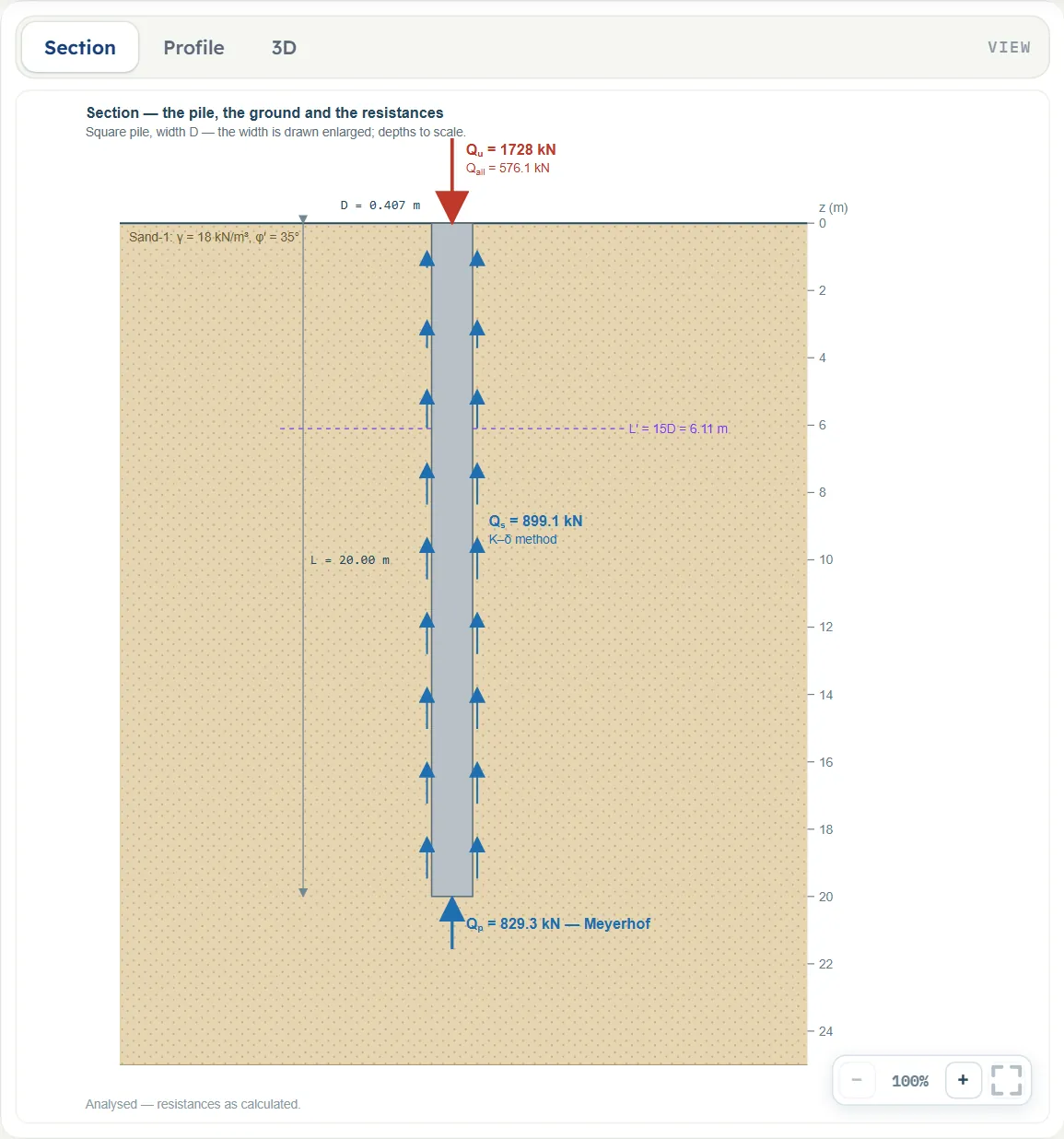
- Section shows the pile in the sand profile, with the water table, the layer boundaries, the critical depth L′ of the K–δ method, the resistances Qp, Qs and Qu (with the method named beside Qp and Qs) and the arrows of the skin friction. You can drag the water table, a layer base, the pile tip or the side of the pile to change them before you analyse.
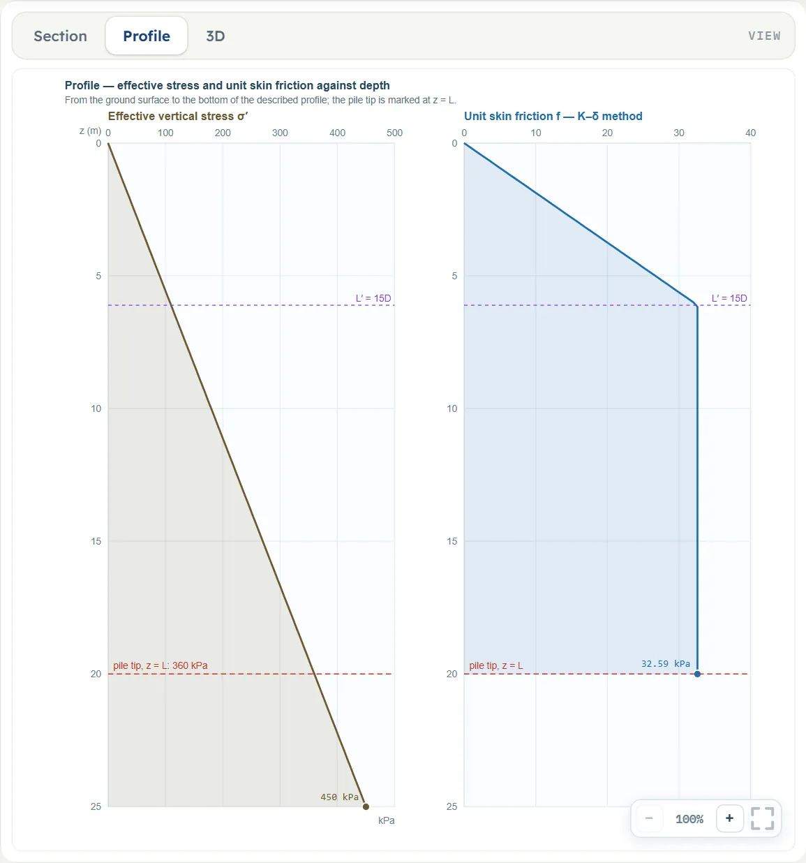
- Profile plots the effective vertical stress σ′ and the unit skin friction f against depth, with the pile tip marked at z = L.
- 3D shows the pile in a block of the ground with the layers and the water table.
Entering the model, section by section
The Model tab has six sections after Model data. Each opens when you click its title; Next and Back at the foot walk you through them. A (?) beside a title or a method opens a help window with a drawing and the formula for that part. The tables below list every field with its symbol, the unit in each unit system, and its default. Where a unit is shown twice or three times, such as m · ft, the units are those of SI · kN, SI · tf and US in turn, and equal ones are merged. A field marked “filled in” carries a value the module works out; you can type over it. Defaults are shown in SI; in another unit system the boxes show the converted values.
Sand layers
Up to eight layers, entered from the ground surface down. The point resistance answers to the layer the tip sits in, and the shaft friction is summed over all the layers the pile passes through. The values in the tables are those of layer 1.
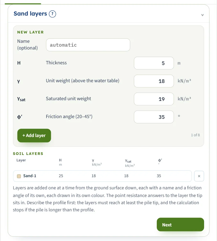
| Field | Symbol | Unit | Default | What to enter |
|---|---|---|---|---|
| Name (optional) | — | — | empty | A name for the layer, for the drawing and the report. Left empty, the layers are called Sand-1, Sand-2 and so on. |
| Unit weight (above the water table) | γ | kN/m³ · t/m³ · pcf | 18 | Unit weight of the sand above the water table, used for the effective stress. |
| Saturated unit weight | γsat | kN/m³ · t/m³ · pcf | 18 | Unit weight of the sand below the water table. Below the water table the module uses γsat − γw. Used only when a water table is present. |
| Friction angle (20–45°) | φ′ | ° | 35 | Effective friction angle of the sand in the layer, at least 20°. Meyerhof’s chart is drawn from 20° to 45°; above 45° the end value is held and a warning says so. |
| Thickness | H | m · ft | 25 | Thickness of the layer. The layers together must reach at least the pile tip; the smallest value accepted is 0.1 m. |
Groundwater
Choose whether there is a water table within the pile length. If there is, enter its depth; below it the effective stress is worked out with the submerged unit weight γsat − γw, with γw = 9.81 kN/m³.
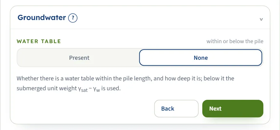
| Choice | Options | Default |
|---|---|---|
| Water table within or below the pile | Present None | None |
| Field | Symbol | Unit | Default | What to enter |
|---|---|---|---|---|
| Water table depth | Dw | m · ft | 100 | Depth of the water table below the ground surface, 0 or more. Shown when the water table is present. |
Pile
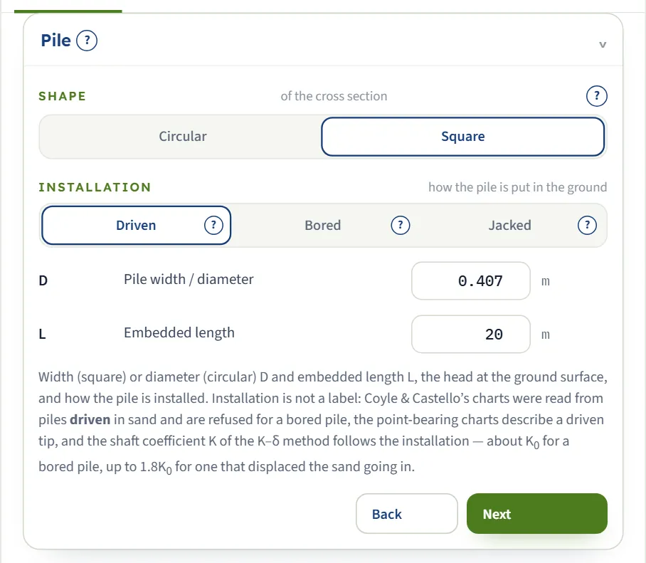
The shape and the installation are choices; the width and the length are numbers. The section gives the area of the tip and the perimeter of the shaft: a square pile has Ap = D² and a perimeter of 4D; a circular one has Ap = πD²/4 and a perimeter of πD.
| Choice | Options | Default |
|---|---|---|
| Shape of the cross section | Circular Square | Square |
| Installation how the pile is put in the ground | Driven Bored Jacked | Driven |
| Field | Symbol | Unit | Default | What to enter |
|---|---|---|---|---|
| Pile width / diameter | D | m · ft | 0.407 | Width of a square pile or diameter of a circular one. It sets the area of the tip and the perimeter of the shaft. |
| Embedded length | L | m · ft | 20 | Embedded length from the ground surface to the tip; the head is taken at the ground surface. |
Point bearing
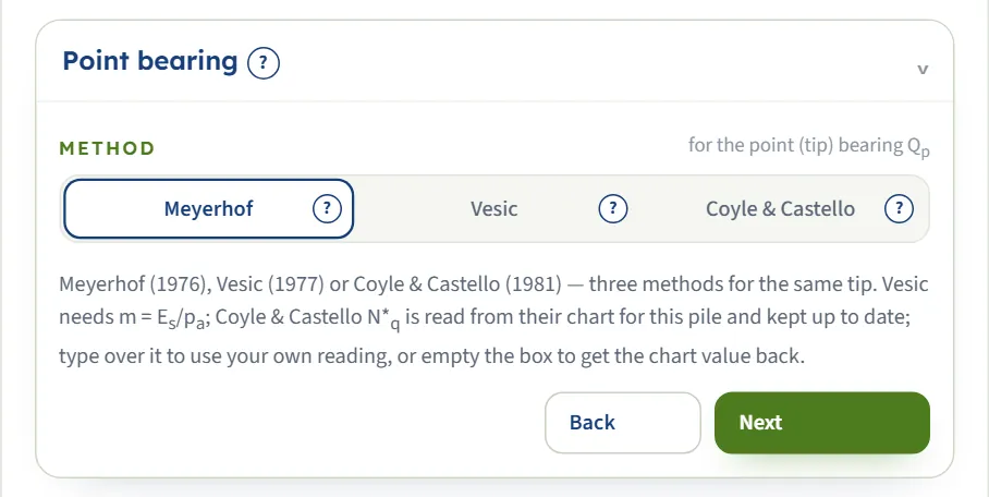
Pick the method for the resistance under the tip. The boxes of the method you choose appear; the others stay out of the way.
| Choice | Options | Default |
|---|---|---|
| Method for the point (tip) bearing Qp | Meyerhof Vesic Coyle & Castello | Meyerhof |
| Field | Symbol | Unit | Default | What to enter |
|---|---|---|---|---|
| Stiffness ratio of the sand | m | — | 250 | The stiffness ratio Es/pa of the sand: about 100–200 loose, 200–500 medium dense, 500–1000 dense. The smallest value accepted is 50. Shown when point-bearing method is Vesic. |
| Coyle & Castello N*q (chart value) | N*q(CC) | — | filled in | Read from the Coyle & Castello chart for this pile’s L/D and φ′ of the tip layer, and kept up to date. Type over it to use your own reading; empty the box to get the chart value back. Shown when point-bearing method is Coyle & Castello. |
Skin friction
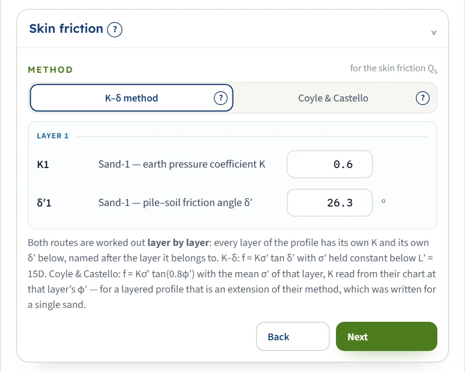
Pick the method for the shaft. Both are worked out layer by layer: every layer of the profile has its own coefficient, named after the layer it belongs to. With the K–δ method each layer also has its own δ′. The values are filled in from the other inputs and can be typed over.
| Choice | Options | Default |
|---|---|---|
| Method for the skin friction Qs | K–δ method Coyle & Castello | K–δ method |
| Field | Symbol | Unit | Default | What to enter |
|---|---|---|---|---|
| Earth pressure coefficient K | K | — | filled in | Earth-pressure coefficient on the shaft in this layer. Filled in as K0 = 1 − sin φ′ for a bored pile and 1.4K0 for a driven or jacked one. The smallest value accepted is 0.2. Shown when skin-friction method is K–δ method. |
| Pile–soil friction angle δ′ | δ′ | ° | filled in | Friction angle between the pile and the sand in this layer. Filled in as 0.75φ′. Shown when skin-friction method is K–δ method. |
| Coyle & Castello K | K(CC) | — | filled in | Coyle & Castello’s coefficient for this layer, read from their chart at the layer’s φ′ and the pile’s L/D; the interface friction is 0.8φ′. Editable. Shown when skin-friction method is Coyle & Castello. |
Design
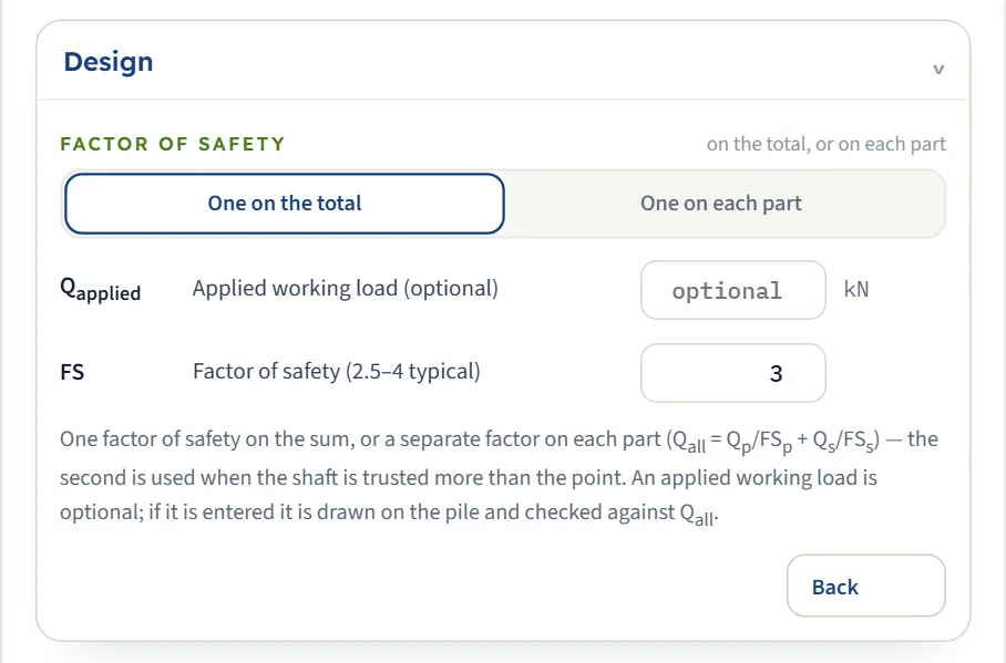
One factor of safety on the sum, or a separate factor on each part: Qall = Qp/FSp + Qs/FSs. The second form is used when the shaft is trusted more than the point. An applied working load is optional.
| Choice | Options | Default |
|---|---|---|
| Factor of safety on the total, or on each part | One on the total One on each part | One on the total |
| Field | Symbol | Unit | Default | What to enter |
|---|---|---|---|---|
| Applied working load (optional) | Qapplied | kN · tf · kip | empty | The working load the pile has to carry. Optional: if it is entered it is drawn on the pile and checked against Qall. |
| Factor of safety (2.5–4 typical) | FS | — | 3 | One factor of safety on Qu. The module’s hint is 2.5 to 4. Shown when factor of safety is One on the total. |
| Factor of safety on the point resistance | FSp | — | 3 | Factor of safety on the point resistance (used with one factor on each part). Shown when factor of safety is One on each part. |
| Factor of safety on the skin friction | FSs | — | 1.5 | Factor of safety on the skin friction; lower than the point factor because the shaft is mobilised at smaller settlements. Shown when factor of safety is One on each part. |
Choosing the methods
The three point-bearing methods and the two skin-friction methods answer the same question in different ways, so the module lets you run one after the other and compare. What each one needs and how it works:
| Method | Unit resistance qp | What it asks for | Notes |
|---|---|---|---|
| Meyerhof (1976) | qp = σ′ N*q ≤ 0.5 pa N*q tan φ′ | φ′ of the tip layer only | N*q is read from his own chart for piles, 20°–45°. The limit ql caps the result; the steps say when it governs. |
| Vesic (1977) | qp = σ̄′o N*σ | φ′ and m = Es/pa | Treats the tip as an expanding cavity: it uses the mean effective stress at the tip and the stiffness of the sand through the reduced rigidity index. |
| Coyle & Castello (1981) | qp = σ′ N*q, no cap | φ′ and the chart value N*q (filled in) | Fitted to field load tests on driven piles in sand; N*q is read against L/D and φ′. Refused for a bored pile. The chart covers φ′ of about 30°–40° (K chart 30°–36°); outside it the end value is used without a message. |
| Method | Unit skin friction f | Coefficients | Notes |
|---|---|---|---|
| K–δ method | f = K σ′ tan δ′, with σ′ held constant below L′ = 15D | K and δ′ for each layer | The friction grows with depth like the effective stress until the critical depth of about 15 pile widths, then stays constant. A fixed rule of thumb, not a chart reading. |
| Coyle & Castello (1981) | f = K σ̄′o tan δ′, δ′ = 0.8φ′ | K read from their chart, for each layer | Uses the mean effective stress of the layer. For a layered profile the module applies it layer by layer, which extends the method, written for a single sand. |
Which should I pick?
- Start with Meyerhof and the K–δ method. They need the least input and are the module’s defaults.
- Use Vesic when you have an estimate of the stiffness of the sand (m). The point resistance then depends on stiffness as well as strength.
- Use Coyle & Castello for driven piles when you want the estimates that come from field load tests. The module refuses it for a bored pile and cautions you for a jacked one.
- Compare. The methods can differ widely. Run them one after the other and keep the results with Quick Save…; the what-if table shows how far they can differ on the example.
Analyze and read the results
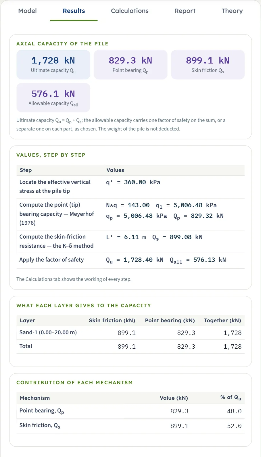
Press Analyze. The bar reports the run, the inputs lock, and the Results tab shows four blocks.
- Axial capacity of the pile. Four cards: the ultimate capacity Qu, the point bearing Qp, the skin friction Qs and the allowable capacity Qall.
- Values, step by step. One row per step of the calculation, with the numbers: the effective stress at the tip, N*q and qp, L′ and Qs, and the factor of safety.
- What each layer gives to the capacity. A table with the skin friction, the point bearing and the total of every layer, and the totals.
- Contribution of each mechanism. The share of the point and of the shaft in Qu as a percentage.
The pile in the Section view now carries Qu, Qall, Qs and Qp, with the method named beside Qs and Qp.
Checking an applied load
If you entered an applied working load Qapplied, the Results tab adds a check: the ratio Qapplied/Qall and a verdict in words. PASS means the applied load is within the allowable capacity; FAIL means it exceeds it. The report says so in words when the load exceeds even Qu. A failing check also raises a warning with advice: lengthen or widen the pile, use more piles, or revisit the factors of safety.
The weight of the pile
The results do not deduct the weight of the pile. If your design basis takes it into account, add it to the applied load, or deduct it from the capacity, as your standard requires.
The Calculations tab and the report
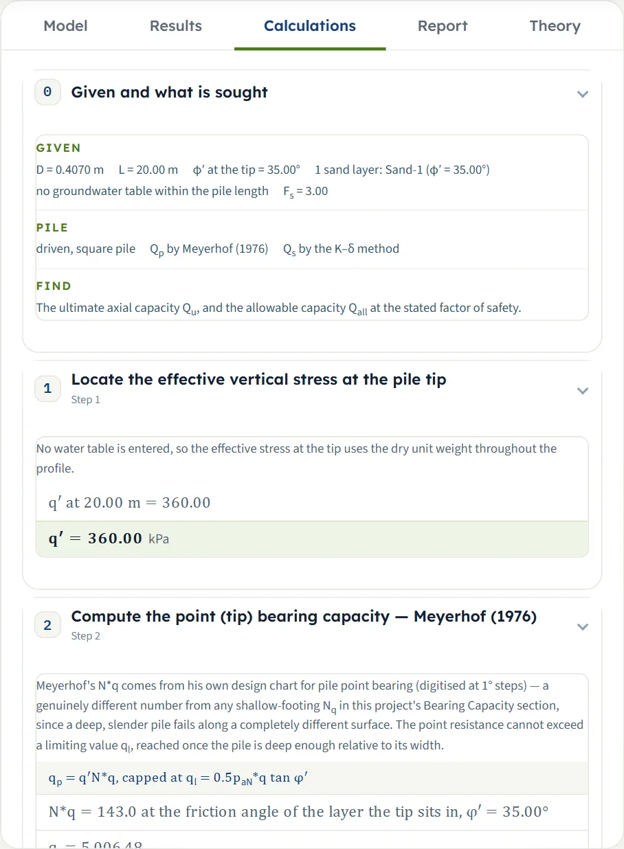
The Calculations tab writes out the working in chapters: Given and what is sought, then one chapter per step, then the Answer in one sentence. For this module the steps are:
- Locate the effective vertical stress at the pile tip — σ′ from the unit weights and the water table.
- Compute the point (tip) bearing capacity — the method you chose, with its factor, the limit if it applies, and Qp.
- Compute the skin-friction resistance — the method you chose, layer by layer, with L′ for the K–δ method, and Qs.
- Apply the factor of safety — Qu and Qall.
- Check the applied working load, when one was entered.
The Report tab turns the same working into a summary report. Fill in the cover (project, location, client, report number, date, prepared by, title, checked by, notes) and press Save as PDF or Download Word (.docx). The report has six parts: 1 Introduction and scope, 2 Input data, 3 Calculation (one part per step), 4 Results, 5 Summary and 6 References. When a run has notes or warnings about the methods, the report adds an Assumptions and notes section after Results (the parts after it move down by one); the units line states the conversion constants.
The Theory tab explains the method: what the pile carries, the effective stress in the profile, the three point-bearing methods, the skin friction and the critical depth, the allowable capacity, and a worked example.
Worked example: the module’s own example
The module opens on this example. Reset to defaults brings it back at any time, so you can follow the numbers on your own screen.
| Section | Input | Value |
|---|---|---|
| Sand layers | One layer, Sand-1 | H = 25 m, γ = γsat = 18 kN/m³, φ′ = 35° |
| Groundwater | Water table | None |
| Pile | Shape, installation | Square, driven |
| Pile | Width, length | D = 0.407 m, L = 20 m |
| Point bearing | Method | Meyerhof |
| Skin friction | Method, coefficients | K–δ; K = 0.6 and δ′ = 26.3° (filled in) |
| Design | Factor of safety | One factor, FS = 3 |
Step 1: the effective stress at the tip
There is no water table, so σ′ = 18 × 20 = 360.00 kPa at the tip.
Step 2: the point bearing, Meyerhof
For φ′ = 35° the chart gives N*q = 143.00, so σ′ N*q = 360 × 143 = 51,480 kPa. That is far above the limiting value ql = 0.5 × 100 × 143 × tan 35° = 5,006.48 kPa, so the limit governs: qp = 5,006.48 kPa. The area of the tip is 0.407² = 0.165649 m², so Qp = 5,006.48 × 0.165649 = 829.32 kN.
Step 3: the skin friction, K–δ
The critical depth is L′ = 15D = 15 × 0.407 = 6.105 m (the module shows 6.11 m). At L′ the effective stress is 18 × 6.105 = 109.89 kPa, so the unit skin friction there is f = 0.6 × 109.89 × tan 26.3° = 32.587 kPa; it grows linearly from zero at the surface to that value, and stays at it down to the tip. With a perimeter of 4 × 0.407 = 1.628 m:
Step 4: the factor of safety
Qu = 829.32 + 899.08 = 1,728.40 kN, and with FS = 3 the allowable capacity is Qall = 1,728.40 / 3 = 576.13 kN. The point carries 48.0 % of the capacity and the shaft 52.0 %.
How each input changes the answer
Each row below changes one thing in the example and runs the module again. The numbers are the results the module gives, in kN, so you can reproduce any row.
| Change | Qp | Qs | Qu | Qall | Why |
|---|---|---|---|---|---|
| The default example | 829.3 | 899.1 | 1,728 | 576.1 | The reference |
| Point bearing by Vesic (m = 250) | 1,721 | 899.1 | 2,620 | 873.3 | No limit on qp |
| Point bearing by Coyle & Castello | 2,087 | 899.1 | 2,986 | 995.4 | N*q from the chart, no limit |
| Skin friction by Coyle & Castello | 829.3 | 1,496 | 2,325 | 775.0 | K from the chart; a note says the chart is projected beyond L/D = 36.1 |
| Both by Coyle & Castello | 2,087 | 1,496 | 3,583 | 1,194 | Both from the field-test charts |
| Bored pile | 829.3 | 644.3 | 1,474 | 491.2 | K = K0 instead of 1.4K0 |
| Jacked pile | 829.3 | 899.1 | 1,728 | 576.1 | Same as driven for the K–δ method |
| Circular section | 651.3 | 706.1 | 1,357 | 452.5 | Area and perimeter are π/4 of the square pile’s |
| Water table at 5 m | 829.3 | 823.5 | 1,653 | 550.9 | Lower σ′ below 5 m; Qp stays at its limit |
| Factor of safety on each part | 829.3 | 899.1 | 1,728 | 875.8 | FSp = 3 and FSs = 1.5 |
| Friction angle 30 | 271.1 | 879.1 | 1,150 | 383.4 | N*q falls, so Qp drops to a third; the shaft barely changes (K rises as φ′ falls, δ′ falls) |
| Friction angle 40 | 2,405 | 875.2 | 3,280 | 1,093 | Qp nearly triples; the shaft barely changes (K falls as φ′ rises) |
| Pile 12 m long | 829.3 | 474.7 | 1,304 | 434.7 | Only the shaft changes |
| Pile 24 m long | 829.3 | 1,111 | 1,941 | 646.9 | Only the shaft changes |
| Width 0.6 m | 1,802 | 1,787 | 3,589 | 1,196 | Larger tip and perimeter |
A bored pile with Coyle & Castello’s point method is not in the table because the module does not run it: it stops and says why (see Messages).
Messages: stops, warnings and notes
The module tells you in plain words when something prevents the calculation, when a result needs care, and what it assumed. There are three kinds.
| Kind | When | Message and what to do |
|---|---|---|
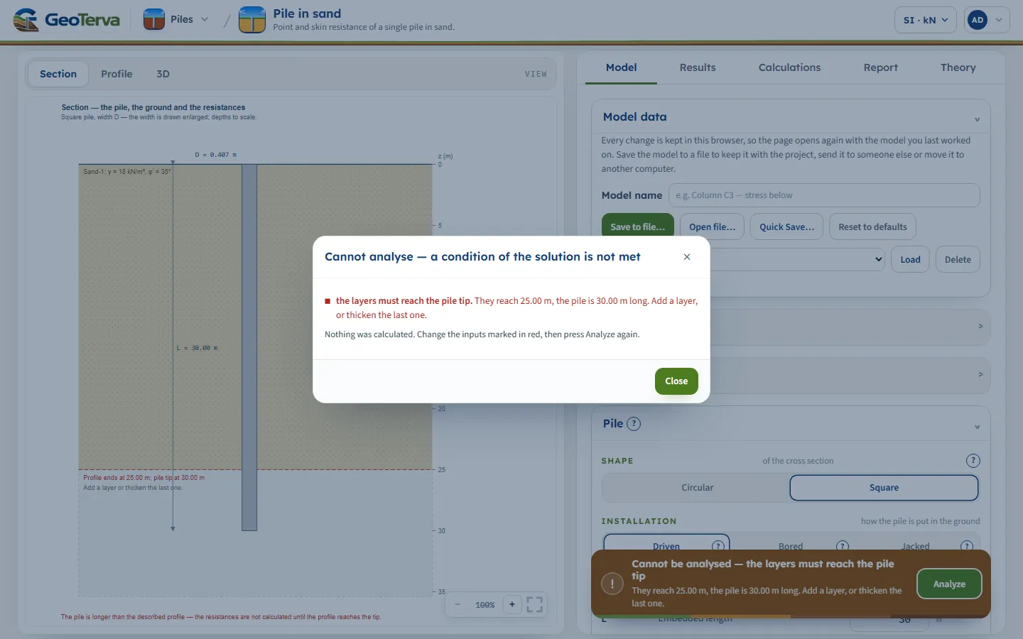
| Stop (brown bar, “Cannot analyse”) | The layers do not reach the pile tip | “The layers must reach the pile tip. They reach 25.00 m, the pile is 30.00 m long.” (the brown bar reads “Cannot be analysed”, the window “Cannot analyse”) Add a layer, or thicken the last one. |
| Stop | Coyle & Castello selected for a bored pile | “Coyle & Castello is calibrated on piles driven in sand; a bored pile is outside it.” Use Meyerhof or Vesic for the point and the K–δ method for the shaft. |
| Warning | Coyle & Castello selected for a jacked pile | “Coyle & Castello is for driven piles; this one is jacked.” Read the result as an estimate, or use the K–δ method. |
| Warning | An applied load larger than Qall | “The pile does not carry the applied load — 173.6% of Qall.” Lengthen or widen the pile, use more piles, or revisit the factors of safety. |
| Stop (input error) | A value below the smallest the field accepts, for example φ′ = 19° | “1 input error: Friction angle (20–45°) (φ′1) must be at least 20°.” Correct the field marked in red. |
| Warning | φ′ above 45° | Meyerhof’s chart is drawn from 20° to 45° only; beyond it the end value is held, not extrapolated. |
| Warning | K above 1.25K0 of the layer for a bored pile | “K is too high for a bored pile”: boring displaces nothing, so K stays near K0. Use K ≈ K0, or say why this shaft carries more. |
| Note | K above 1.8K0 for a driven or jacked pile | The table of K runs from K0 to 1.8K0; keep a higher value if a load test or local practice supports it. |
| Note | The tip is exactly on a layer boundary | The point resistance is worked from the layer below the boundary, the soil beneath the base; the layer above contributes shaft friction only. |
| Note | The profile ends less than 2D below the tip | The deepest layer is taken to continue below, with the same properties, because the point resistance comes from the soil just under the tip. |
| Note | Coyle & Castello beyond the chart | The chart is projected beyond L/D = 36.1 (for K); the coefficient boxes stay editable, so a value read off the figure can be used instead. |
| Note | Bored pile | The friction angle entered at the toe is taken to describe the sand after drilling; no further reduction is applied for the bored construction. |
The Warnings (or Notes) button on the green bar lists them after a run. When a run has notes or warnings about the methods, the report adds an Assumptions and notes section after the results; the check on an applied load appears in the calculation and in the summary.
Good practice and common mistakes
- Describe the sand below the tip. The point resistance depends on the soil at and just below the tip. Take the profile to at least two pile widths below it, or accept the module’s assumption that the last layer continues.
- Match the installation to the pile. It changes K and decides whether Coyle & Castello is open. A driven pile entered as bored gets the lower K and so a lower shaft resistance; a bored pile entered as driven gets the higher K and a higher one.
- Do not expect the point bearing to grow with the length when the limit governs. When σ′ N*q is above ql, the limit caps qp, and a longer pile adds shaft only.
- Run more than one method. The spread of the answers is information. Keep each run with Quick Save….
- Keep the layer φ′ an effective friction angle from your investigation, not a total-stress parameter.
- Check the units after you switch the system: type values in the units shown beside the boxes.
- Read the notes. They list what the module assumed; they are printed in the report.
Frequently asked questions
How do I calculate the capacity of a pile in sand?
The ultimate capacity is the sum of the point bearing under the tip and the skin friction along the shaft, Qu = Qp + Qs. The allowable capacity is Qu divided by a factor of safety. In GeoTerva’s Pile in sand module you describe the sand layers, the pile and the methods, press Analyze, and the module gives Qp, Qs, Qu and Qall with every step of the working.
What is the difference between Meyerhof, Vesic and Coyle & Castello for the point?
Meyerhof reads N*q from a chart against φ′ and caps the unit resistance at a limiting value. Vesic treats the tip as an expanding cavity and also needs the stiffness ratio m = Es/pa. Coyle & Castello read N*q from a chart fitted to field load tests on driven piles, against L/D and φ′, with no cap. On the module’s example they give 829 kN, 1,721 kN and 2,087 kN.
What is the critical depth L′ = 15D?
In the K–δ method the unit skin friction grows with depth like the effective stress until a critical depth of about 15 pile widths, and is held constant below it. The module draws it as a dashed line on the pile and uses L′ = the smaller of 15D and L.
What values of K and δ′ does the module use?
They are filled in for each layer: K = K0 = 1 − sin φ′ for a bored pile and 1.4K0 for a driven or jacked pile, and δ′ = 0.75φ′. You can type over any of them. With the Coyle & Castello method K is read from their chart and δ′ is 0.8φ′.
Why does the point bearing not change when I make the pile longer?
Meyerhof’s method limits the unit point resistance to ql = 0.5 pa N*q tan φ′. When the limit governs, as in the module’s example, a longer pile adds shaft friction but no point resistance. The steps say when the limit governs.
Can I use the Coyle & Castello method for a bored pile?
No. Their charts were read from driven piles, so the module stops and asks you to change the method. For a jacked pile it allows the method with a caution.
Does the module deduct the weight of the pile?
No. The capacity is the resistance of the ground; the weight of the pile is not deducted, and the module states this under its results.
How many layers can I enter, and what does the water table do?
Up to eight sand layers. A water table within the pile length makes the module use the submerged unit weight γsat − γw below it for the effective stress, which lowers the shaft friction.
Which units does the module use?
SI · kN, SI · tf or US, switchable in the header at any time, even after Analyze. The report states the units and the conversion constants.
Does it check group effects, settlement or lateral load?
This module treats one pile under axial load. Use Pile group for the group effect and settlement, and Pile under lateral load for the lateral response.
How do I compare two designs?
Run the first, press Quick Save…, press Edit inputs, change a value, run again and quick-save again. Load in the Model tab brings any version back. Save to file… keeps a version with the project.