

What the module calculates
MSE wall checks a mechanically stabilized earth wall: a wall of free-draining granular fill with galvanized steel strips, geotextile sheets or geogrids laid in it level by level behind a facing. The fill takes the compression, the reinforcement the tension, and the friction between them holds the two together. The module gives the tension of every reinforcement level and checks each level for rupture, for pullout beyond the failure surface and, if you give its strength, for the connection to the facing. It then checks the reinforced block as a gravity wall for overturning, the eccentricity of the resultant, sliding on the base and bearing of the foundation soil on Meyerhof’s effective width, and repeats the checks under an earthquake.
Two procedures are offered. The simplified method (FHWA / AASHTO) raises the lateral stress for steel strips (Kr = 1.7 Ka at the top falling to 1.2 Ka at 6 m) and uses a bilinear failure surface 0.3 H behind the facing in the upper half of the wall; for a geosynthetic it takes Ka and the Rankine surface. Rankine at every depth (the source) takes Ka at every depth and the Rankine wedge from the toe for every kind of reinforcement.
What you can describe
- A wall height H, a reinforcement length L (the same at every level, from the back of the facing) and the vertical spacing SV; for strips also the horizontal spacing SH.
- Galvanized steel strips (width, thickness, yield strength, corrosion per year and design life), geotextile sheets or a geogrid (ultimate strength, three reduction factors, and for a geogrid the coverage ratio).
- The pullout resistance factor F* and the scale effect correction α, which the module fills in and you can type over from pullout tests.
- The reinforced fill, the retained fill behind the block and the foundation soil.
- One uniform surcharge on the whole surface, taken as a live load.
- A horizontal seismic coefficient kh.
- The five required factors of safety, and optionally the strength of the connection to the facing.
Which module for which wall
- A reinforced-concrete cantilever wall: Cantilever RC wall.
- A stone masonry or plain concrete gravity wall: Gravity wall.
- Granular fill reinforced level by level with strips, sheets or grids: this module.
- The Rankine, Coulomb and Mononobe–Okabe coefficients are explained in the Lateral earth pressure manuals; other surface loads in the Surcharge loads manuals; the bearing equation in the Bearing capacity manuals.
The module gives the internal and the external checks of the wall. Combine them with a slope stability analysis of the whole wall and the ground below it, which the module reminds you of in every run (see Messages).
Before you start: what you need
Have these ready from your design and your ground investigation:
| What and source | Notes |
|---|---|
| The wall Your design | Height H (1 to 30 m), reinforcement length L and the spacings SV (0.2 to 2 m) and, for strips, SH. The practice takes L not less than 0.7 H and not less than 2.4 m; the module cautions you when it is shorter. |
| The reinforcement The maker’s data | For strips: width, thickness as placed, yield strength, the loss of thickness per year and the design life. For a geosynthetic: the ultimate tensile strength from the wide-width test, the reduction factors for installation damage, creep and chemical and biological degradation, and for a geogrid the coverage ratio. |
| Pullout data Pullout tests, if you have them | The factors F* and α fill themselves; type over them with the values of your tests. |
| The soils Your ground investigation | Unit weight and friction angle of the reinforced fill and of the retained fill; unit weight, friction angle and cohesion of the foundation soil. |
| The loads Your design loading | A uniform surcharge on the surface, and the seismic coefficient kh if the earthquake governs. |
| The required factors Your design basis | Rupture, pullout, overturning, sliding and bearing; the module opens on 1.8 (strips) or 1.5 (sheets), 1.5, 2, 1.5 and 2.5. The strength of the connection per strip or per metre of wall, if it is known. |
Quick start in eight steps
- Open the module and choose the units
Open MSE wall from the Retaining Walls family. Pick SI · kN, SI · tf or US in the header; you can change it at any time, also after Analyze.
- Choose the procedure and describe the wall
In Wall and reinforcement layout choose Simplified method (FHWA / AASHTO) or Rankine at every depth (the source) and enter H, L, SV and, for strips, SH.
- Choose the reinforcement
In Reinforcement press Galvanized steel strips, Geotextile sheets or Geogrid and enter its data. Pullout resistance has F* and α, already filled in.
- Describe the soils
In Fills and Foundation soil enter the unit weights and the strength. The retained fill follows the reinforced fill until you type over it.
- Add the surcharge and the earthquake
In Surcharge enter q and press + Add load; in Earthquake enter kh (0 means no earthquake).
- Set the required factors
In Required factors check the five factors and, if you know it, enter the strength of the connection.
- Press Analyze
Press Analyze at the foot of the Model tab. The bar reads Analysed, the inputs lock and the drawing colours every level by its factors. If the run has warnings, a Warnings window opens by itself. A mistake in the inputs opens Cannot analyse with what to correct.
- Read the results and take the working
The Results tab gives the cards, the tension and the length the checks ask for and the table of the levels; Calculations writes out every step with your numbers; Report saves a PDF or a Word file.
The screen: views, chips and zoom
The layout is the one every GeoTerva module shares (workspace guide): the drawing on the left, the tabs Model, Results, Calculations, Report and Theory on the right. The drawing has four views, chosen above it:
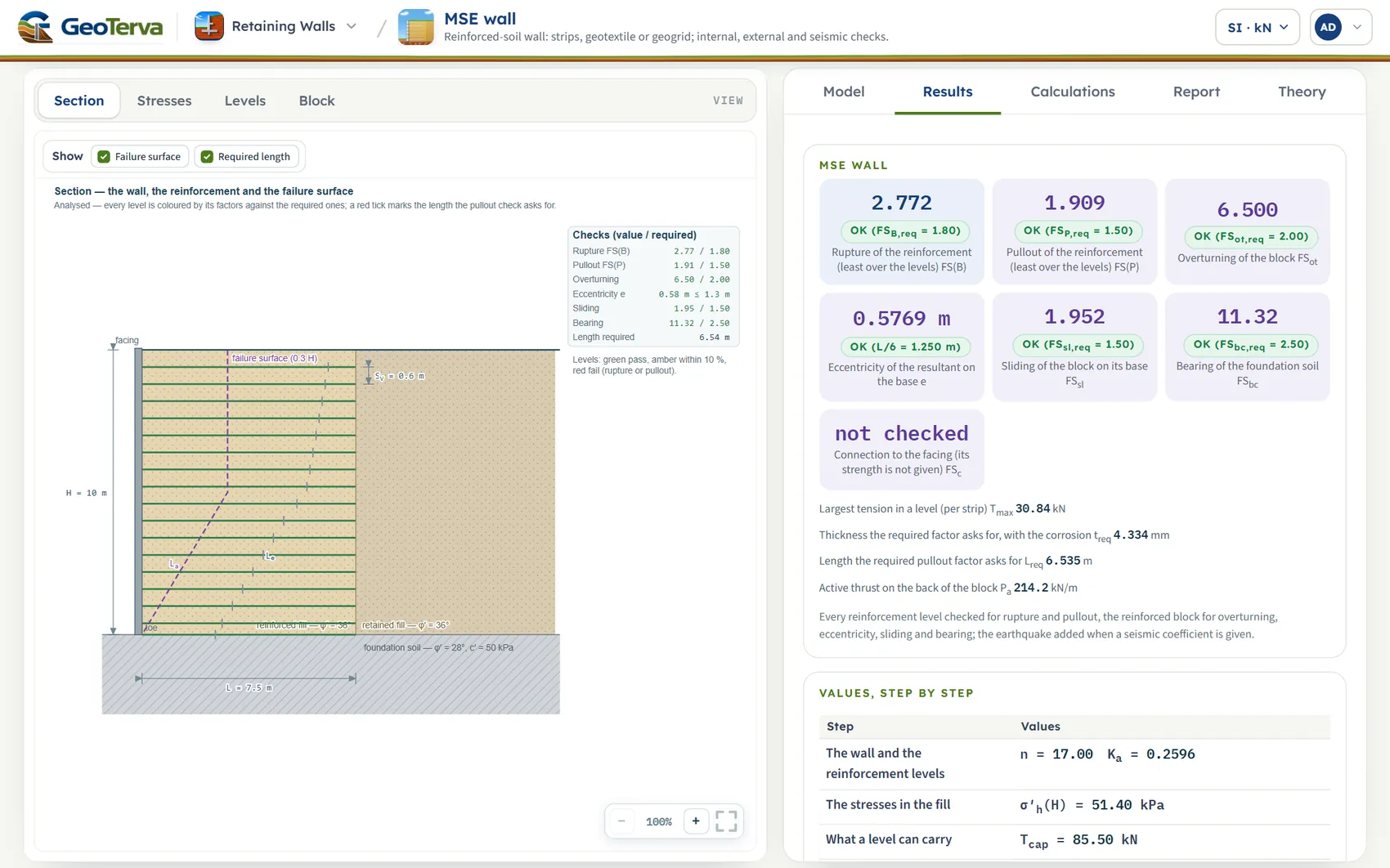
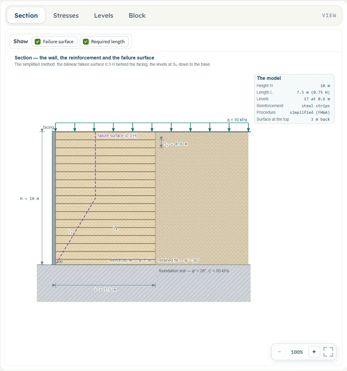
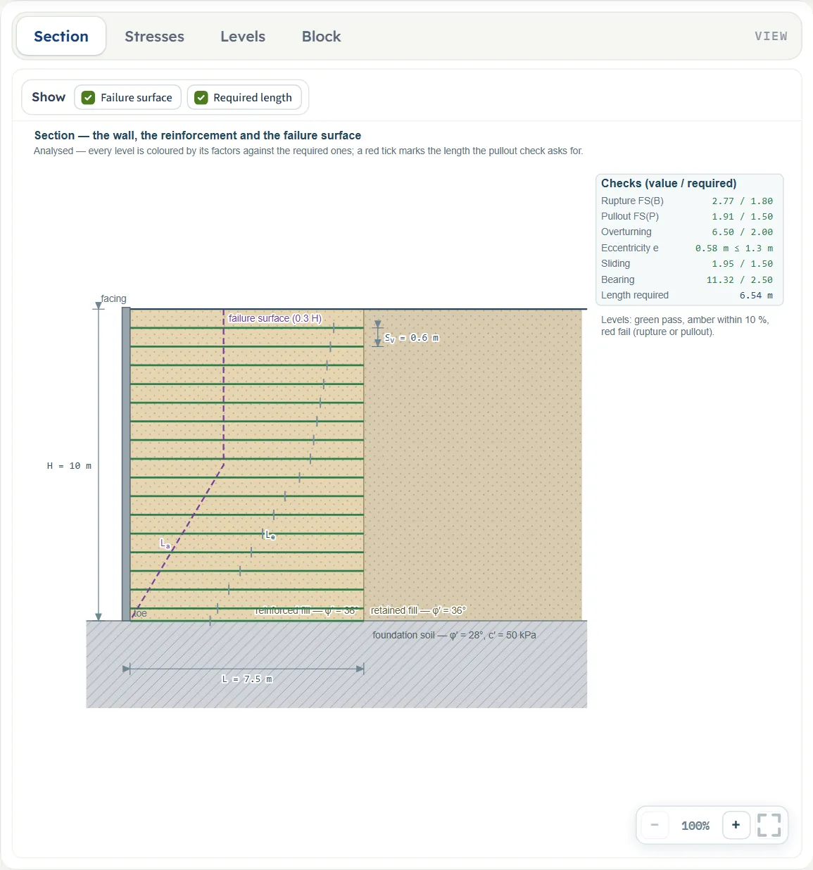
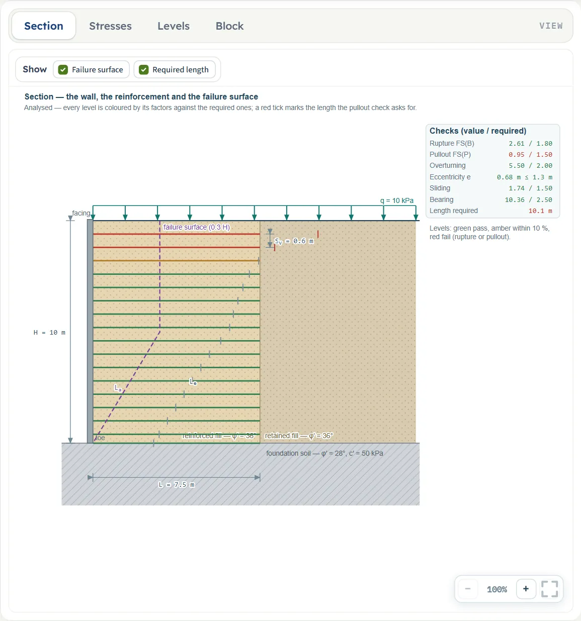
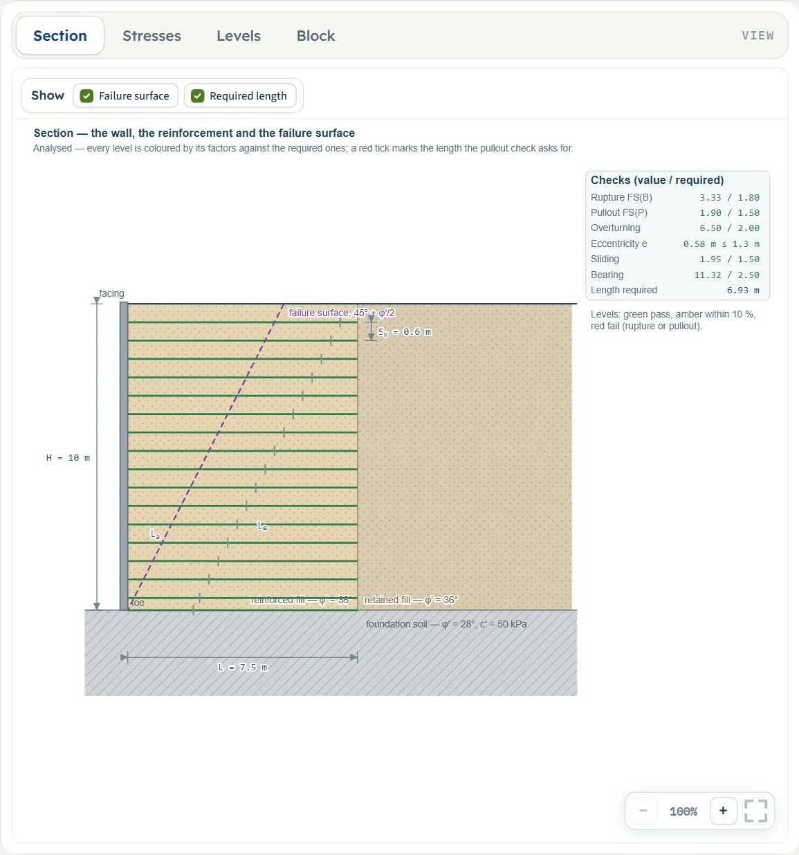
- Section is the wall in section: the facing, the reinforcement levels with their length L, the retained fill, the foundation soil, the failure surface of the chosen procedure, the surcharge and the dimensions H, SV and L. Before Analyze it follows your inputs. After Analyze every level is coloured by its factors (green passes, amber is within 10 % of the required value, red fails), a red tick marks the length the pullout check asks for, and a small box lists the checks as value / required.
- Stresses (after Analyze) draws the vertical stress, the lateral stress and the tension of every level against what it can carry, part by part: the fill and the surcharge.
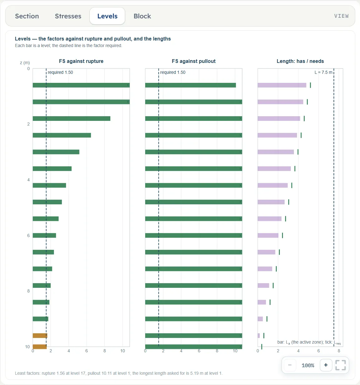
- Levels (after Analyze) draws one bar per level: the factor against rupture, the factor against pullout, each with a dashed line at the factor required, and the length each level has against the length it needs.
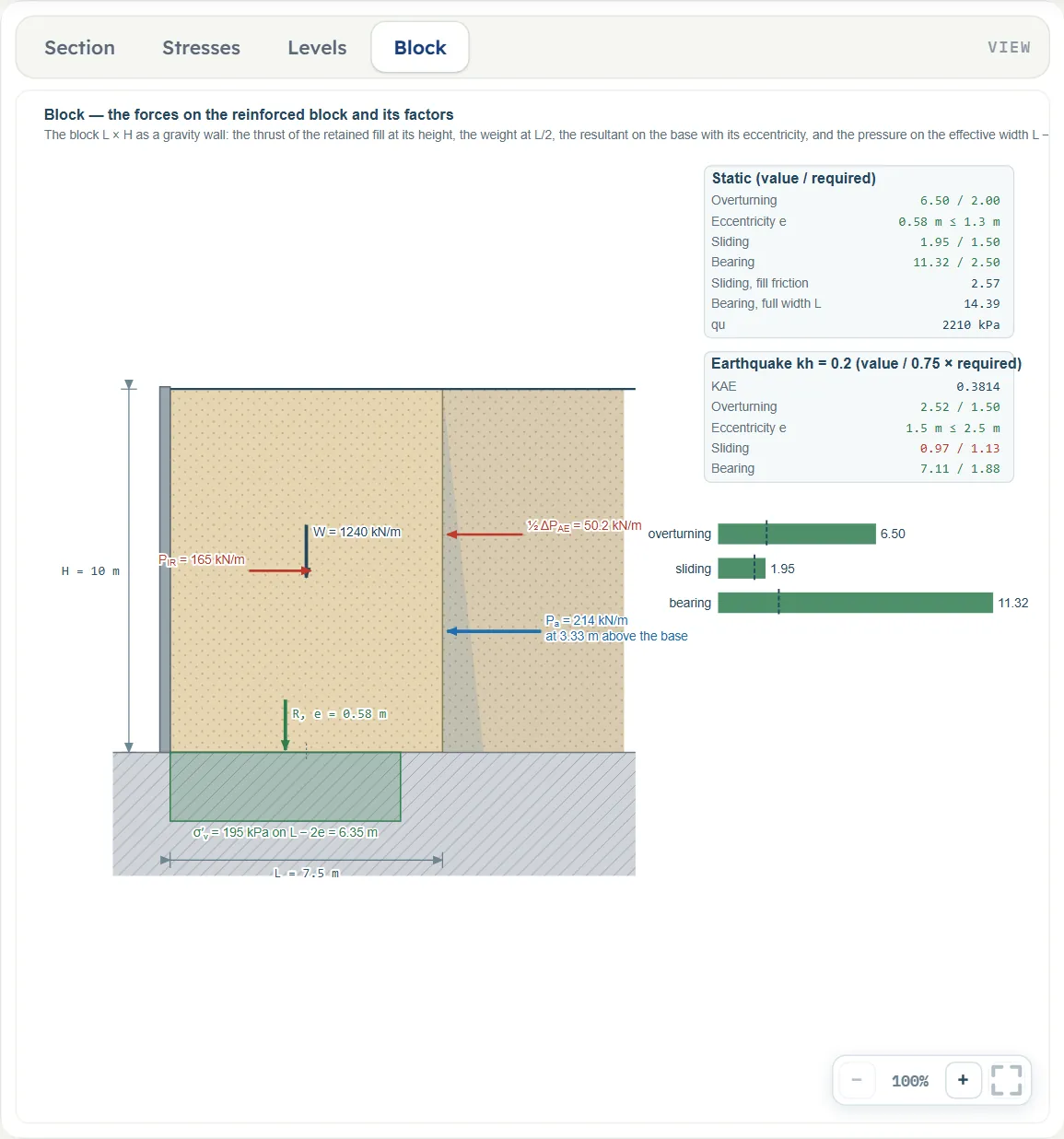
- Block (after Analyze) draws the reinforced block as a gravity wall: the thrust of the retained fill and where it acts, the weight, the resultant on the base with its eccentricity, the bearing pressure on the effective width and the factors against the required ones; with an earthquake the seismic forces and factors stand beside them.
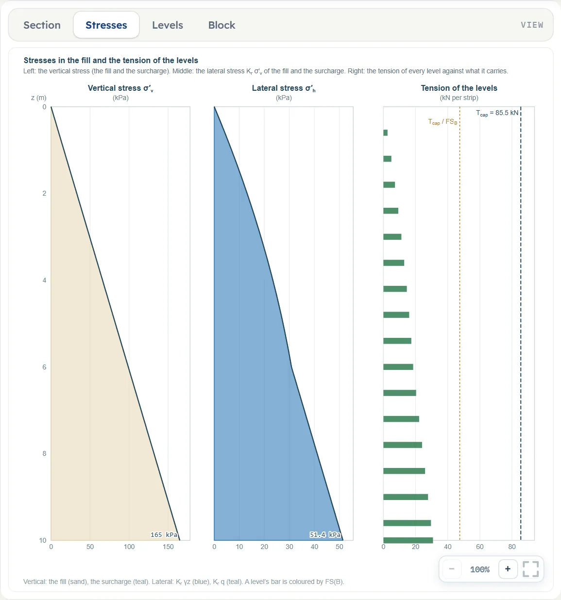
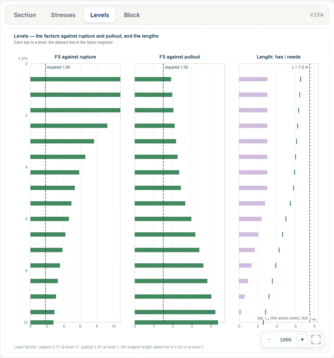
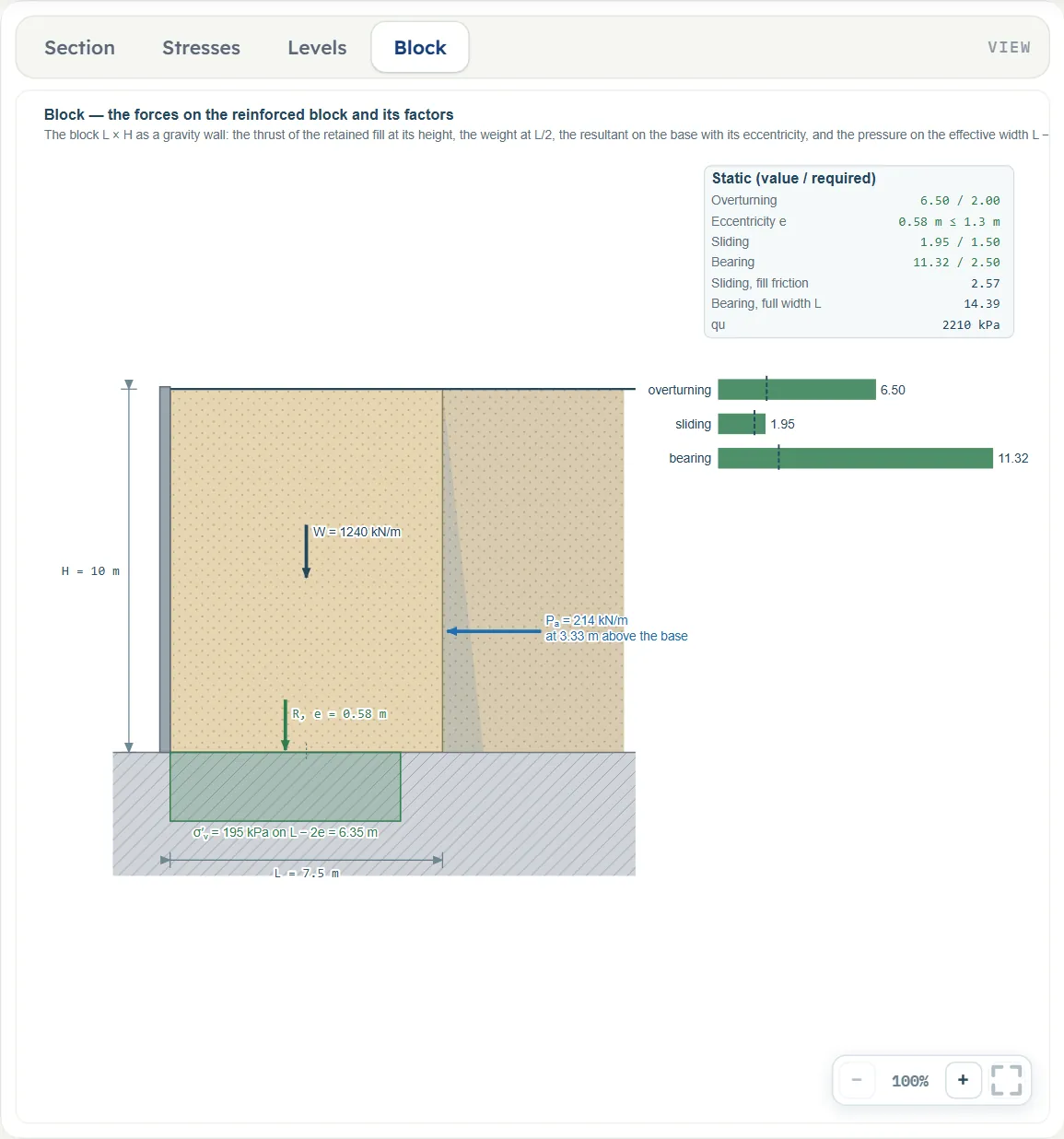
Show chips
The Section view has two chips, Failure surface and Required length, both on when the module opens. The first draws the failure surface; the second draws the red ticks of the length the pullout check asks for after Analyze. The other views have no chips.
Zoom
Each view has −, a percentage and + at the lower right and a button that fits the whole drawing in the pane.
Picking, dragging and locking
Nothing on the drawing can be dragged: the wall is entered in the Model tab. With a surcharge added, the load on the Section drawing can be picked before Analyze: pressing it opens the Surcharge section with the load in the form (Editing · Load 1), the same as pressing its row in the table. After Analyze the inputs are locked: the bar says “The inputs are locked. Edit inputs clears the results; the unit system can still be changed.” Edit inputs unlocks the model, clears the results and takes the drawing back to the inputs.
Units
Switching to US or SI · tf converts the boxes, the cards, the tables, the working and the drawings (for example H = 32.8 ft and the eccentricity 1.893 ft in US). A value typed in one system is converted in the boxes of another and may show unrounded, for example H = 32.8084 ft for 10 m.
Entering the model, section by section
The Model tab has nine sections: Model data, Wall and reinforcement layout, Reinforcement, Pullout resistance, Fills, Foundation soil, Surcharge, Earthquake and Required factors. Each opens when you click its title; Next and Back at the foot walk you through them, and Analyze waits below the last one. Model data and Wall and reinforcement layout are open when the module opens; the others open when you click their title. A value that the module fills in itself carries a small tag beside its label (from the fill, default or same as the fill). Where a unit is written twice, such as m · ft, the units are those of SI · kN, SI · tf and US in turn. Defaults are given in SI.
Model data
The first section holds the model name, Save to file…, Open file…, Quick Save… with its list and Load and Delete, and Reset to defaults. Quick Save… asks for a name for the version and puts it in the list with the date; Reset to defaults brings the default model back at once. The workspace guide describes them: workspace guide.

Wall and reinforcement layout
Procedure has Simplified method (FHWA / AASHTO) (the default) and Rankine at every depth (the source). The four fields below describe the wall; SH appears for strips only. The levels lie at SV, 2 SV, … down to the base; when H is not a multiple of SV the last level is placed at the base and still carries the fill of the height SV (the module notes it).
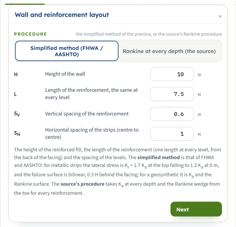
| Field | Default | What to enter |
|---|---|---|
| Height of the wall H · m · ft | 10 | From 1 to 30 m. |
| Length of the reinforcement, the same at every level L · m · ft | 7.5 | Measured from the back of the facing; at least 0.5 m. The practice asks for 0.7 H and not less than 2.4 m. |
| Vertical spacing of the reinforcement SV · m · ft | 0.6 | From 0.2 to 2 m, and not more than H. |
| Horizontal spacing of the strips (centre to centre) SH · m · ft | 1 | At least 0.1 m; the strip width must be less than it. Strips only. |
Reinforcement
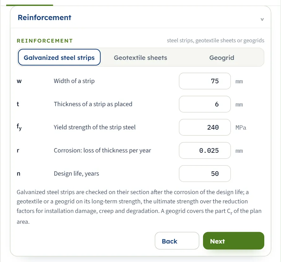
Reinforcement has Galvanized steel strips (default), Geotextile sheets and Geogrid; the fields below it change with the choice. A strip is checked on its section after the corrosion of the design life, a sheet on its long-term strength. Changing the kind also changes the values the module fills in: F*, α and the required factor against rupture.
| Field | Default | What to enter |
|---|---|---|
| Width of a strip w · mm · in | 75 | At least 5 mm; less than SH. |
| Thickness of a strip as placed t · mm · in | 6 | At least 0.5 mm. |
| Yield strength of the strip steel fy · MPa · kg/cm² · ksi | 240 | At least 10 MPa. |
| Corrosion: loss of thickness per year r · mm · in | 0.025 | Zero or more. The thickness lost over the design life, r × n, is taken off the strip before it is checked. |
| Design life, years n | 50 | From 0 to 200. |
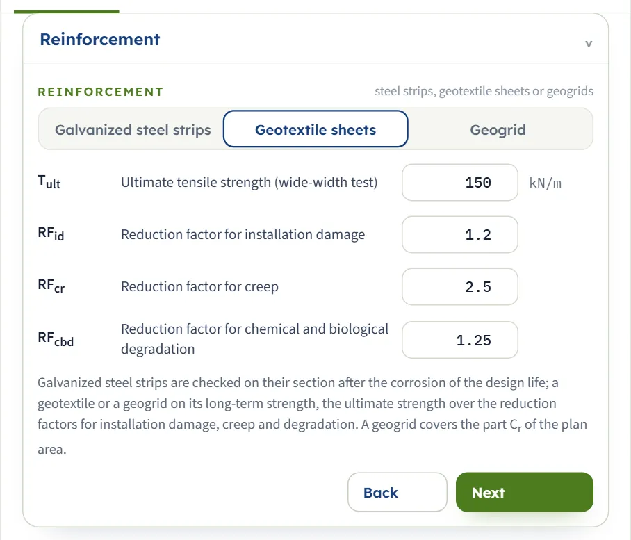
The long-term strength is Tult / (RFid RFcr RFcbd) per metre; with the defaults 150 / (1.2 × 2.5 × 1.25) = 40 kN/m. A geogrid level carries that strength times Cr per metre of wall: 40 × 0.8 = 32 kN/m.
| Field | Default | What to enter |
|---|---|---|
| Ultimate tensile strength (wide-width test) Tult · kN/m · tf/m · kip/ft | 150 | At least 1. Per metre of the width of the sheet. |
| Reduction factor for installation damage RFid | 1.2 | From 1 to 3. |
| Reduction factor for creep RFcr | 2.5 | From 1 to 5. |
| Reduction factor for chemical and biological degradation RFcbd | 1.25 | From 1 to 3. |
| Coverage ratio of the geogrid Cr | 0.8 | From 0.05 to 1; the part of the plan area a level of geogrid covers. Geogrid only. |
Pullout resistance
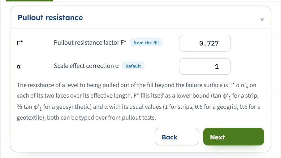
The resistance of a level to being pulled out of the fill beyond the failure surface is F* α σ′v on each of its two faces over its effective length. F* is filled in with the tag from the fill and α with the tag default; type over them with the values of pullout tests. If you clear F*, the module fills it in again.
| Field | Default | What to enter |
|---|---|---|
| Pullout resistance factor F* | 0.727 (strips) · 0.484 (sheets) | From 0.01 to 3. Filled in as tan φ′1 for a strip and ⅔ tan φ′1 for a geosynthetic. |
| Scale effect correction α | 1 (strips) · 0.8 (geogrid) · 0.6 (geotextile) | From 0.1 to 1. |
Fills
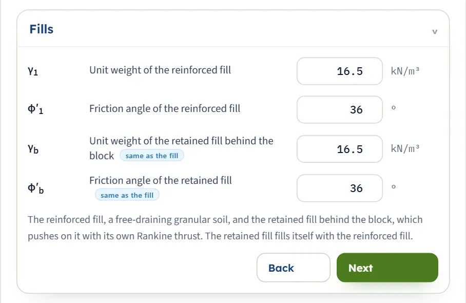
The reinforced fill is a free-draining granular soil. The retained fill behind the block pushes on it with its own Rankine thrust. It fills itself with the values of the reinforced fill; type over it for another soil. When you change φ′1, the retained fill’s φ′b, F* and the pullout values follow, unless you have typed over them.
| Field | Default | What to enter |
|---|---|---|
| Unit weight of the reinforced fill γ1 · kN/m³ · t/m³ · pcf | 16.5 | From 10 to 25 kN/m³. |
| Friction angle of the reinforced fill φ′1 · ° | 36 | From 20° to 45°. |
| Unit weight of the retained fill behind the block γb · kN/m³ | 16.5 | From 10 to 25. Follows the reinforced fill. |
| Friction angle of the retained fill φ′b · ° | 36 | From 15° to 45°. Sets the thrust on the back of the block. Follows the reinforced fill. |
Foundation soil
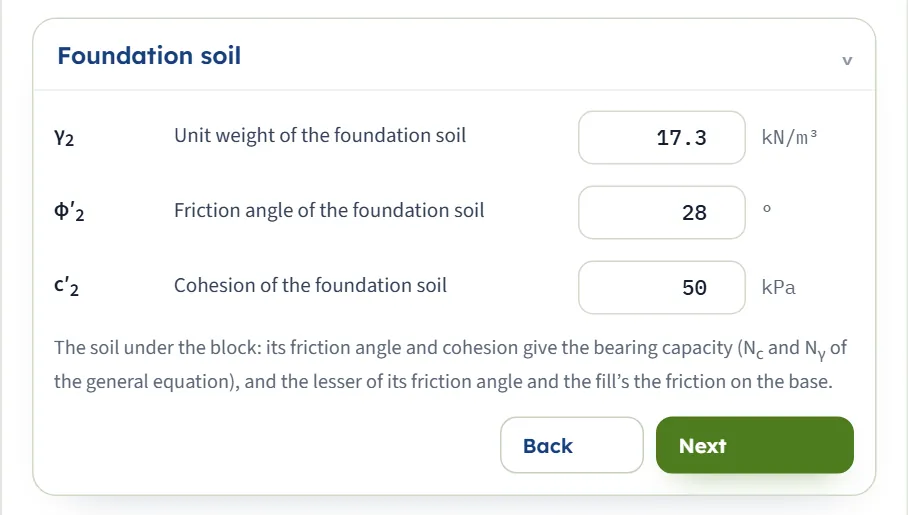
The soil under the block. Its friction angle and cohesion give the bearing capacity; the lesser of its friction angle and that of the reinforced fill gives the friction on the base, taken as ⅔ of it with no cohesion.
| Field | Default | What to enter |
|---|---|---|
| Unit weight of the foundation soil γ2 · kN/m³ | 17.3 | From 10 to 25. |
| Friction angle of the foundation soil φ′2 · ° | 28 | From 0° to 45°. |
| Cohesion of the foundation soil c′2 · kPa · kg/cm² · psf | 50 | Zero or more. |
Surcharge
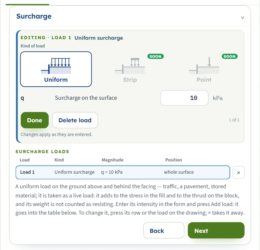
The section is a form over a table. Kind of load shows Uniform; Strip and Point are shown faded with the tag SOON. Enter q and press + Add load: the load goes into the table (Load 1 · Uniform surcharge · q = 10 kPa · whole surface), and the counter reads 1 of 1; there is one load. The New load form starts at q = 10 kPa, and the model starts with no load. Press the row or the load on the drawing to change it (Editing · Load 1, with Done and Delete load; changes apply as they are entered); × takes it away.
The load is taken as a live load: it adds q to the vertical stress and Kr q to the lateral stress at every depth and Ka q H to the thrust on the back of the block, and its weight is not counted as resisting, nor in the pullout resistance.

| Field | Default | What to enter |
|---|---|---|
| Surcharge on the surface q · kPa · t/m² · ksf | 10 (the form) | Zero or more. Acts on the whole surface above the reinforced and the retained fill. |
Earthquake
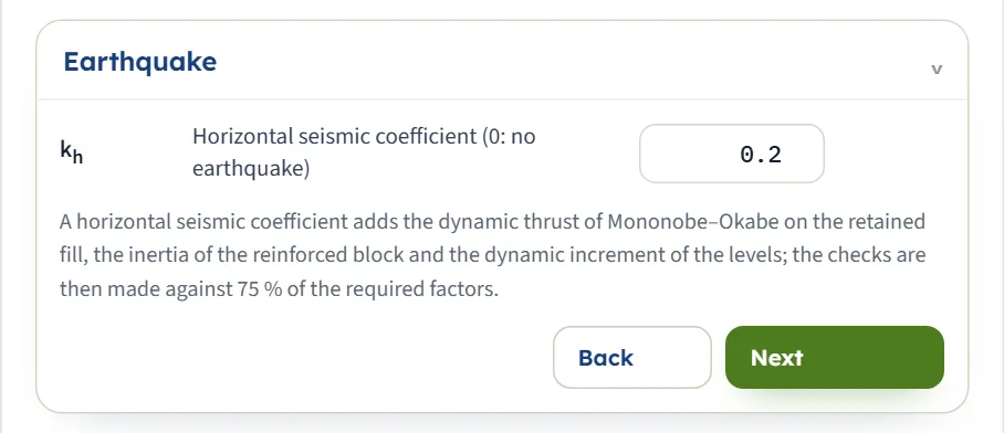
A horizontal seismic coefficient adds, to the static checks, the dynamic thrust of Mononobe–Okabe on the retained fill, the inertia of the reinforced block and the dynamic increment of the levels; the checks are then made against 75 % of the required factors. The module takes the vertical coefficient as zero.
| Field | Default | What to enter |
|---|---|---|
| Horizontal seismic coefficient (0: no earthquake) kh | 0 | From 0 to 0.6. Zero means no earthquake. It must be less than tan φ′b (see Messages). |
Required factors
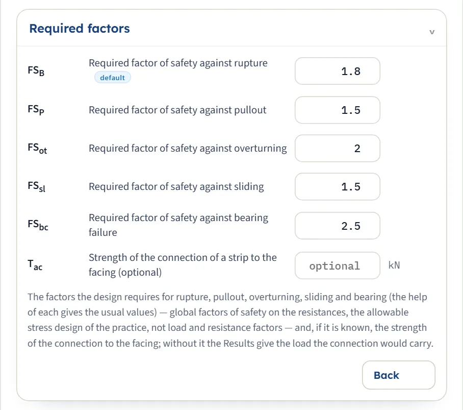
The factors the design requires are global factors of safety on the resistances (allowable stress design), one for each check. The strength of the connection is optional; without it the connection is not checked, and the Results card says not checked.
| Field | Default | What to enter |
|---|---|---|
| Required factor of safety against rupture FSB | 1.8 (strips) · 1.5 (sheets) | From 1 to 10. Fills itself when you change the kind of reinforcement. |
| against pullout FSP | 1.5 | From 1 to 10. |
| against overturning FSot | 2 | From 1 to 10. |
| against sliding FSsl | 1.5 | From 1 to 10. |
| against bearing failure FSbc | 2.5 | From 1 to 10. |
| Strength of the connection of a strip to the facing (optional) Tac · kN · tf · kip | empty | At least 0.1. Per strip. Strips only. |
| Strength of the connection to the facing per metre of wall (optional) Tac · kN/m | empty | At least 0.1. Sheets only. The long-term strength from connection tests. |
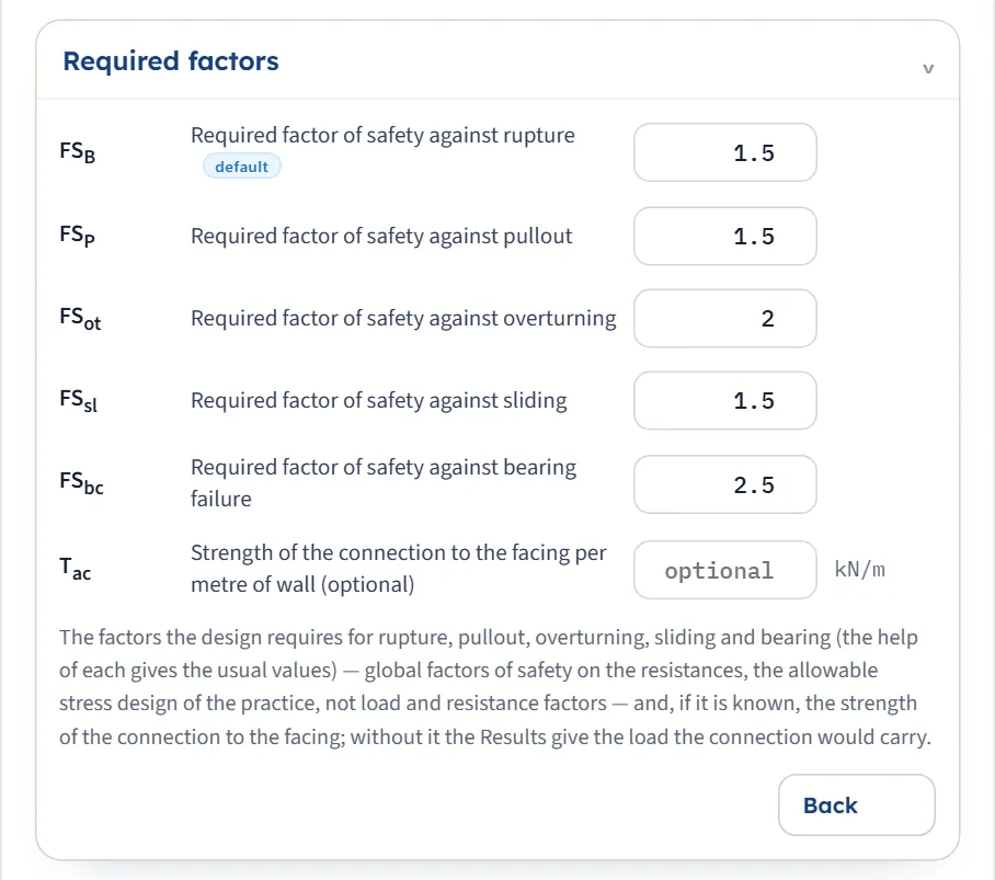
A value outside the range shown stops the analysis (see Messages). The five required factors work as limits on the cards: a check reads OK at or above its required value and NOT OK below it.
Choosing the procedure and the reinforcement
The two procedures
The procedure decides the lateral stress in the fill and the failure surface. On the default wall (strips, H = 10 m) the simplified method gives the largest tension Tmax = 30.84 kN and the factors against rupture and pullout 2.772 and 1.909; Rankine at every depth gives Tmax = 25.70 kN and the factors 3.327 and 1.898. The block checks (6.500 · 1.952 · 11.32) are the same in both, because the thrust on the back of the block is Rankine in both. In the table, Simplified is the simplified method (FHWA / AASHTO) and Rankine is Rankine at every depth.
| Simplified | Rankine | |
|---|---|---|
| Lateral stress, strips | Kr = 1.7 Ka at the top, falling to 1.2 Ka at 6 m, then constant | Ka at every depth |
| Lateral stress, sheets | Ka | Ka |
| Failure surface, strips | La = 0.3 H down to H/2, then 0.6 (H − z) | La = (H − z) / tan(45° + φ′1/2) |
| Failure surface, sheets | The Rankine surface | The Rankine surface |
Here z is the depth of the level and La its distance from the facing to the failure surface; the effective length Le = L − La is the part that resists pullout.
The kind of reinforcement
- Strips are checked for rupture on w teff fy with teff = t − r n; with the defaults 0.075 × 0.00475 × 240 000 = 85.50 kN per strip. The Results then give the thickness the required factor asks for, with the corrosion allowance.
- Geotextile sheets are checked on Tall = Tult / (RFid RFcr RFcbd) per metre. The Results then give the vertical spacing the required factor allows at the level of the largest tension, and the lap length at the facing.
- Geogrid is checked on Tall Cr per metre of wall. The Results give the vertical spacing the required factor allows.
Changing only the kind of reinforcement on the default wall (everything else as it opened) gives the factors against rupture and pullout 1.556 and 10.11 for geotextile sheets and 1.245 and 10.78 for the geogrid; the geogrid reads NOT OK against its 1.50 required, and the Warnings window opens (see Messages). Both kinds of sheet take F* = 0.484 (⅔ tan φ′1), with α = 0.6 for the geotextile and 0.8 for the geogrid, which is why their pullout factors differ from the strips’.
Analyze and read the results
Press Analyze at the foot of the Model tab. The module stays on the Model tab: the bar reads Analysed — the MSE wall calculated (with the number of warnings, if any), the inputs lock and the drawing shows the results; open the Results tab to read them. A mistake in the inputs opens Cannot analyse instead. When the run has warnings the Warnings window opens by itself; a run with notes only does not open it, and the notes are behind the Notes button of the bar.
The cards
The first card block gives the static checks; each card shows the value, OK or NOT OK with the required value, and the name of the check:
- Rupture of the reinforcement FSB: the least over the levels, against the factor required (FSB,req ).
- Pullout of the reinforcement FSP: the least over the levels.
- Overturning of the block FSot.
- Eccentricity of the resultant on the base e: OK when it is within L/6.
- Sliding of the block on its base FSsl.
- Bearing of the foundation soil FSbc.
- Connection to the facing FSc: not checked until you give the strength of the connection; then it is judged against the factor required for rupture.
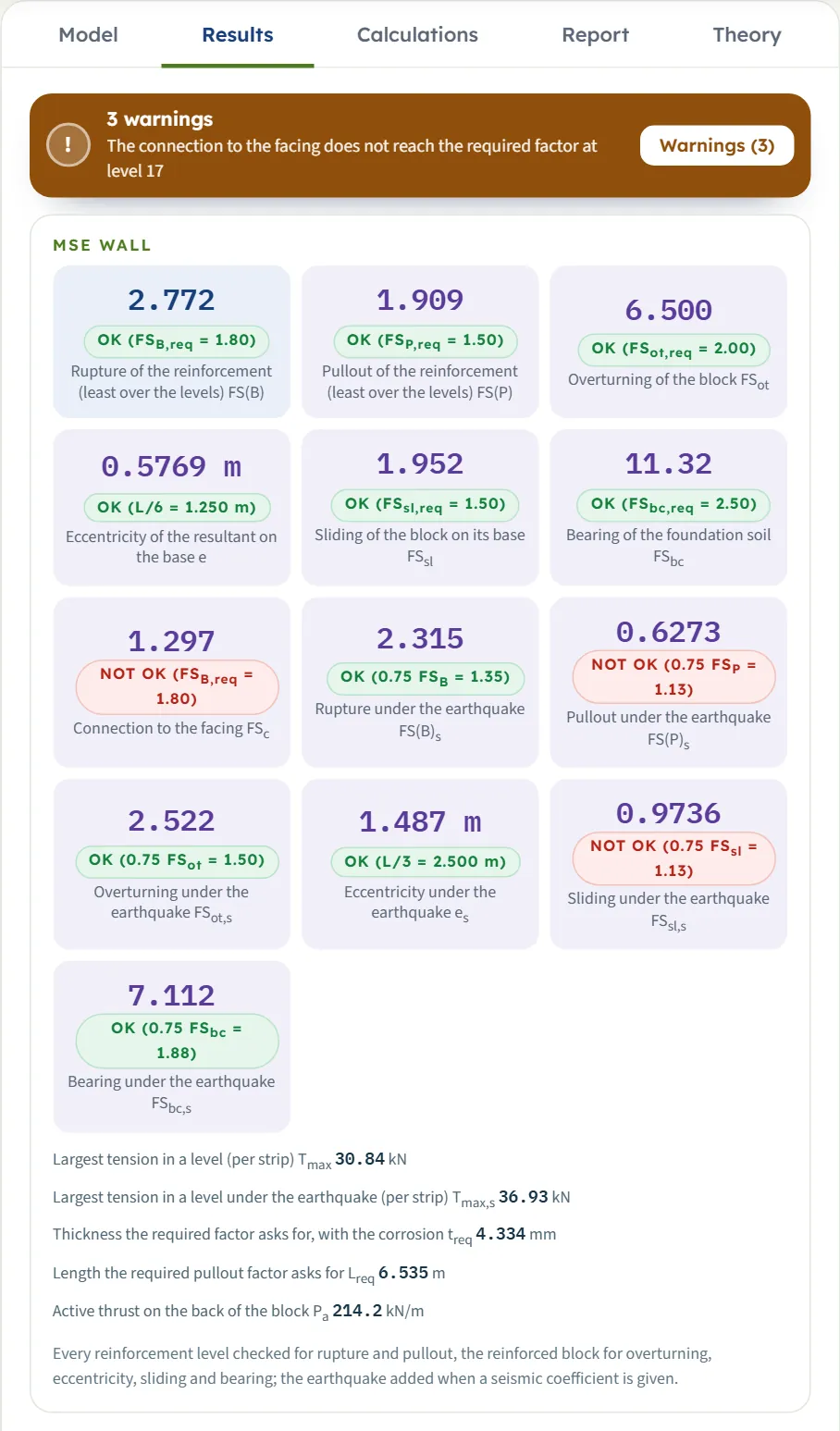
With a seismic coefficient the cards add Rupture under the earthquake FSB,s , Pullout under the earthquake FSP,s , Overturning under the earthquake, Eccentricity under the earthquake (within L/3) , Sliding under the earthquake and Bearing under the earthquake, each against 75 % of its required factor.
The lines below the cards
- Largest tension in a level Tmax (per strip for strips, per metre for sheets); with an earthquake also Tmax,s .
- Strips: the thickness the required factor asks for, with the corrosion treq. Sheets: the vertical spacing the required factor allows SV,req at the level of the largest tension, and, for a geotextile, the lap length at the facing.
- The length the required pullout factor asks for Lreq: compare it with the L provided.
- The active thrust on the back of the block Pa in kN/m.
The Values, step by step table gives the key value of every step of the working, and The reinforcement levels table lists every level: depth z, Kr/Ka, the vertical and lateral stress, the tension T, FSB, the distances La and Le, the pullout resistance Pr, FSP and Lreq. With an earthquake a second table lists the dynamic increment Tmd, the total Ttot and the earthquake factors of every level.
Warnings and notes
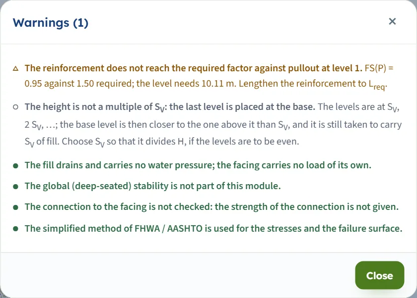
Warnings (a △ mark) say what does not reach its required value and what to do about it; notes (○ and ●) state what the run assumes. The window lists them all.
For the default wall with a 10 kPa surcharge the first warning reads: “The reinforcement does not reach the required factor against pullout at level 1. FS(P) = 0.95 against 1.50 required; the level needs 10.11 m. Lengthen the reinforcement to Lreq.”
Calculations, Report and Theory
Calculations
The Calculations tab writes the working with your numbers. It opens with Given and what is sought, then the steps:
- The wall and the reinforcement levels: the number of levels, Ka, and for the simplified method the failure surface and the active zone.
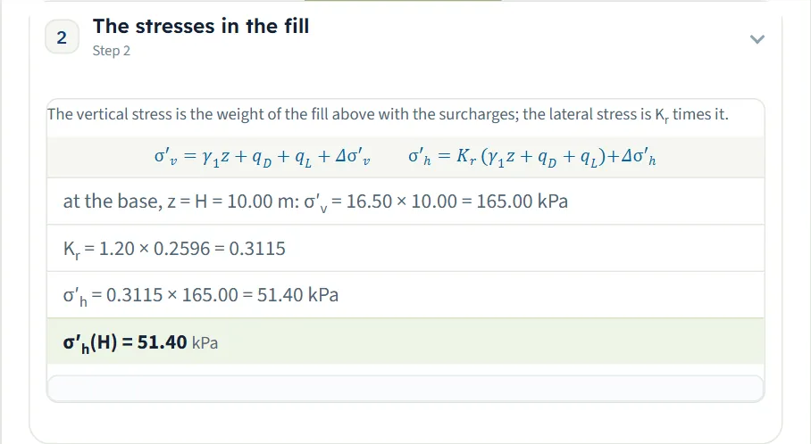
- The stresses in the fill: σ′v, Kr and σ′h at the base.
- What a level can carry: Tcap for a strip after the corrosion, or Tall and Tcap for a sheet, and the pullout resistance Pr.
- Internal stability, level by level: the tension, the factors against rupture and pullout, the lengths, the thickness or the spacing the factors ask for, and the table of the levels.
- The connection to the facing (only when its strength is given).
- External stability of the reinforced block: the thrust Pa, the moments about the toe, overturning with the eccentricity, sliding and bearing on the effective width L′ = L − 2e.
- The earthquake (only when kh is given): Mononobe–Okabe, the inertia of the block, the factors and the levels under the earthquake.
Notes and warnings close the tab. Every step has its equations, then your numbers inserted.
Report
The Report tab has the Report cover (project, location, client, report number, date, prepared by, title or qualification, checked by and optional notes; kept in this browser and with the model file) and Save as PDF and Download Word (.docx). The report has the parts 1. Introduction and scope, 2. Input data, 3. Calculation (the steps of the Calculations tab), 4. Results, 5. Assumptions and notes, 6. Summary and 7. References. The summary lists the checks that do not reach their required value, in words.

Theory
The Theory tab explains how the module checks the wall in fourteen sections: A reinforced-soil wall, The stresses in the fill, The failure surface and the lengths, The tension of a level, Rupture, Pullout, The reinforced block: overturning, Sliding, Bearing, The earthquake, Reading the results, A worked example, What the module assumes, and what it does not do and References. Open one section or all.
Worked example: the default wall
The module opens on this wall: H = 10 m, L = 7.5 m, SV = 0.6 m, SH = 1 m, steel strips 75 × 6 mm with fy = 240 MPa, r = 0.025 mm/year over 50 years, F* = 0.727 and α = 1, reinforced and retained fill γ = 16.5 kN/m³ and φ′ = 36°, foundation soil γ = 17.3 kN/m³, φ′ = 28°, c′ = 50 kPa, the simplified method, no surcharge, no earthquake, and the required factors 1.8, 1.5, 2, 1.5 and 2.5. There are 17 levels.
Internal stability
| Quantity | Working | Module |
|---|---|---|
| Ka | tan²(45° − 36°/2) | 0.2596 |
| Kr/Ka at 6 m and below | 1.2 | 1.20 |
| σ′v at the base | 16.5 × 10 | 165.0 kPa |
| σ′h at the base | 1.2 × 0.2596 × 165.0 | 51.40 kPa |
| Tmax (level 17) | 51.40 × 0.6 × 1 | 30.84 kN per strip |
| Tcap | 0.075 × (0.006 − 0.025 × 50/1000) × 240 000 | 85.50 kN |
| FSB | 85.50 / 30.84 | 2.772 |
| La at the top | 0.3 × 10 | 3.00 m |
| Pr at level 1 | 2 × 0.075 × 0.727 × 1 × 9.9 × (7.5 − 3.0) | 4.858 kN |
| FSP at level 1 | 4.858 / 2.544 | 1.909 |
| Lreq at level 1 | 3.00 + 1.5 × 2.544 / (2 × 0.075 × 0.727 × 9.9) | 6.535 m |
External stability
| Quantity | Working | Module |
|---|---|---|
| Pa | ½ × 0.2596 × 16.5 × 10² | 214.2 kN/m |
| Mo | 214.18 × 10/3 | 713.9 kN·m/m |
| Weight | 16.5 × 10 × 7.5 | 1237.5 kN/m |
| FSot | (1237.5 × 3.75) / 713.9 | 6.500 |
| e | 7.5/2 − (4640.6 − 713.9) / 1237.5 | 0.5769 m |
| FSsl | 1237.5 × tan(⅔ × 28°) / 214.18 | 1.952 |
| Pressure on L′ = 7.5 − 2 × 0.577 | 1237.5 / 6.346 | 195 kPa |
| FSbc (the lesser of the two factors governs) | (50 × 25.80 + ½ × 17.3 × 6.346 × 16.72) / 195 | 11.32 |
Every value above agrees with an independent hand calculation from the formulas the Calculations tab states (the stated F* = 0.727 is tan 36° rounded to three places, so a hand value of FSP from tan 36° differs in the last figure: 1.908). All six checks read OK; the connection reads not checked because its strength is not given. The warnings window does not open: the run has notes only (five of them).
US and SI · tf: the same wall
Switching the units does not change a factor. The cards give the same FSB, FSP, FSot, FSsl and FSbc; the quantities with a dimension convert:
| Quantity SI · kN | US | SI · tf |
|---|---|---|
| e 0.5769 m | 1.893 ft | 0.5769 m |
| Tmax (per strip) 30.84 kN | 6.934 kip | 3.145 tf |
| treq 4.334 mm | 0.1706 in | 4.334 mm |
| Lreq 6.535 m | 21.44 ft | 6.535 m |
| Pa 214.2 kN/m | 14.68 kip/ft | 21.84 tf/m |
In US the default boxes show H = 32.8084 ft, L = 24.6063 ft, SV = 1.9685 ft, SH = 3.28084 ft, w = 2.95276 in, t = 0.23622 in, fy = 34.8091 ksi, γ = 105.037 pcf and c′ = 1044.27 psf for the foundation soil. In SI · tf: fy = 2447.32 kg/cm², γ = 1.68253 t/m³, c′ = 0.509858 kg/cm².
The same wall under an earthquake, kh = 0.2
With kh = 0.2 and a connection strength of 40 kN per strip, the static cards stay as above and the earthquake adds the figures below (retained fill φ′ = 36°). ψ = tan⁻¹ 0.2 = 11.31° and KAE = 0.3814.
| Quantity | Working | Module |
|---|---|---|
| Dynamic increment ΔPAE | ½ × 16.5 × 10² × (0.3814 − 0.2596) | 100.45 kN/m |
| Inertia of the block PIR | ½ × 0.2 × 16.5 × 10² | 165.00 kN/m |
| Ps | 214.18 + 0.5 × 100.45 + 165.00 | 429.41 kN/m |
| FSot,s | 4640.6 / 1840.3 | 2.522 (1.50 required) |
| es | 1.487 m (L/3 = 2.500 m) | |
| FSsl,s | 1237.5 × tan(⅔ × 28°) / 429.41 | 0.9736 (1.13 required): NOT OK |
| FSbc,s | 7.112 (1.88 required) | |
| FSB,s | 2.315 (1.35 required) | |
| FSP,s | 0.6273 (1.13 required): NOT OK | |
| Connection FSc | 40 / 30.84 | 1.297 (1.80 required): NOT OK |
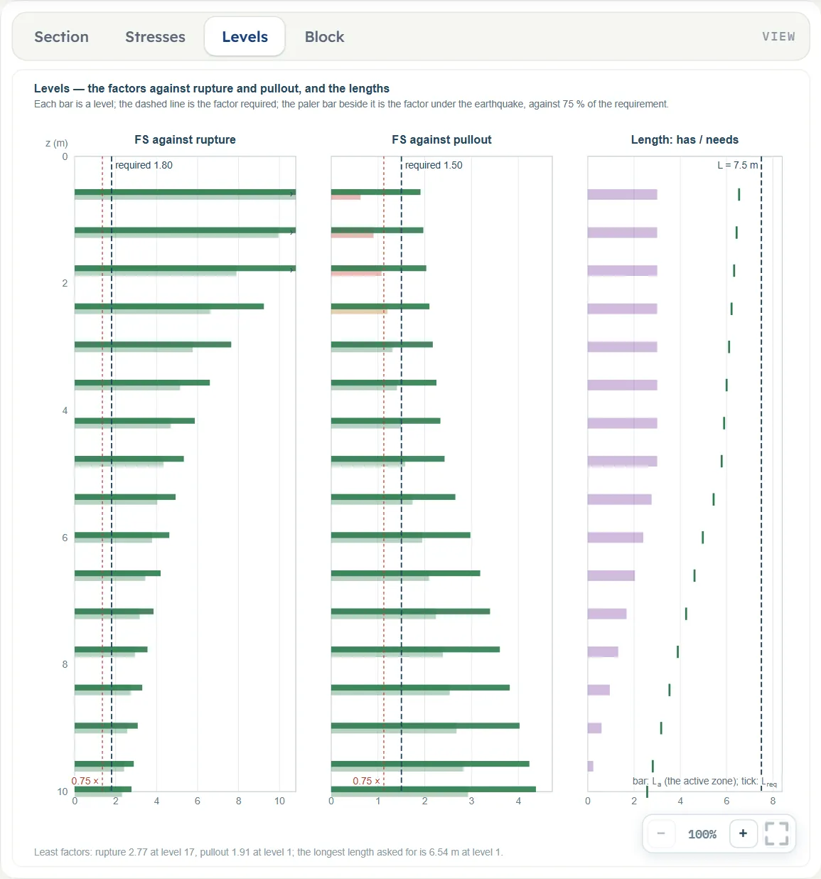
The warnings window then lists three warnings: the connection (“The connection to the facing does not reach the required factor at level 17. FSc = 1.30 against 1.80. Use a stronger connection, or bring the levels closer.”), the block under the earthquake and the level under the earthquake.
How each input changes the answer
Each row changes one input of the default wall and leaves the rest as the module opened (strips 75 × 6 mm, simplified method, H = 10 m, L = 7.5 m, SV = 0.6 m, SH = 1 m, γ1 = 16.5 kN/m³, φ′1 = 36°, φ′b = 36°, foundation γ = 17.3 kN/m³, φ′2 = 28°, c′2 = 50 kPa, no surcharge, no earthquake). The values are read from the module after Analyze. The middle column lists the least FSB (rupture) and the least FSP (pullout) over the levels, one under the other (required 1.80 and 1.50); the last column lists overturning, sliding and bearing, one under the other (required 2.00, 1.50 and 2.50).
| Change | Rupture Pullout | Overturning Sliding Bearing |
|---|---|---|
| Default wall | 2.772 1.909 | 6.500 1.952 11.32 |
| L = 5 m (instead of 7.5) | 2.772 0.8486 | 2.889 1.301 6.986 |
| L = 9 m | 2.772 2.546 | 9.360 2.342 13.28 |
| L = 3 m | 2.772 0 | 1.040 0.7808 0.3046 |
| SV = 0.4 m | 4.158 2.835 | 6.500 1.952 11.32 |
| SV = 1 m | 1.663 1.169 | 6.500 1.952 11.32 |
| SH = 0.5 m | 5.544 3.819 | 6.500 1.952 11.32 |
| Strip width w = 100 mm | 3.696 2.546 | 6.500 1.952 11.32 |
| Strip thickness t = 4 mm | 1.605 1.909 | 6.500 1.952 11.32 |
| Corrosion r = 0.05 mm/year | 2.043 1.909 | 6.500 1.952 11.32 |
| Yield strength fy = 355 MPa | 4.100 1.909 | 6.500 1.952 11.32 |
| φ′1 = 32° (F*, φ′b follow) | 2.342 1.387 | 5.492 1.649 10.79 |
| φ′1 = 40° (F*, φ′b follow) | 3.310 2.631 | 7.761 2.330 11.80 |
| φ′b = 30° only | 2.772 1.909 | 5.063 1.520 10.51 |
| γ1 = 19 kN/m³ (γb follows) | 2.407 1.909 | 6.500 1.952 9.832 |
| φ′2 = 20° | 2.772 1.909 | 6.500 1.369 5.320 |
| φ′2 = 35° | 2.772 1.909 | 6.500 2.492 25.35 |
| c′2 = 0 | 2.772 1.909 | 6.500 1.952 4.706 |
| F* typed as 1.0 | 2.772 2.626 | 6.500 1.952 11.32 |
| α = 0.8 | 2.772 1.527 | 6.500 1.952 11.32 |
| Surcharge q = 10 kPa | 2.614 0.9498 | 5.500 1.741 10.36 |
| Surcharge q = 20 kPa | 2.472 0.6322 | 4.767 1.571 9.543 |
| H = 14 m (L stays 7.5 m) | 1.980 1.400 | 3.316 1.394 6.191 |
| H = 6 m (L stays 7.5 m) | 4.620 2.418 | 18.06 3.253 22.08 |
What the rows show
- The length L works on pullout and on the block, not on rupture: at 5 m the pullout factor falls to 0.8486 and the eccentricity 0.8654 m exceeds L/6; at 3 m the top levels reach no further than the failure surface (their effective length is zero) and the least pullout factor reads 0.
- The spacing SV and SH set the area each level carries, so they scale the tension: halving SH to 0.5 m doubles the rupture factor, 5.544. They do not enter the block checks.
- The strip (w, t, r, fy) sets the rupture factor; the width also enters the pullout resistance (2 w …), the thickness does not.
- φ′1 changes the tension, the failure surface, the weight and the pullout factor at once, and moves F* and φ′b with it, so the row combines several effects; φ′b alone changes only the thrust on the block.
- The foundation soil works on sliding (through φ′2, the lesser friction angle) and on bearing (φ′2, c′2); overturning does not change.
- A surcharge adds to the tension and the thrust but not to the pullout resistance or the resisting weight, because it is taken as a live load: the pullout factor falls to 0.9498 with 10 kPa.
Messages
The messages are quoted as the module shows them. A stop message appears in the Cannot analyse window; warnings and notes are in the Warnings window and the bar.
Stop: Cannot analyse
- A value is outside its range or empty: Cannot analyse — 1 input error, then, for example, “Vertical spacing of the reinforcement (SV) must be at most 2 m.” or “Height of the wall (H) is missing.”
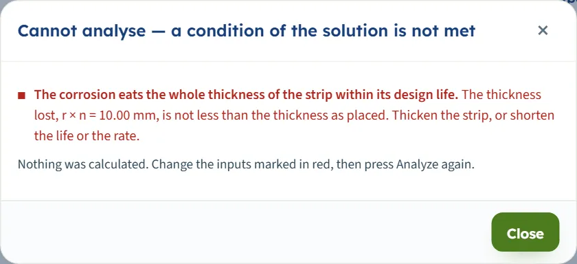
- The corrosion takes the whole strip: Cannot analyse — a condition of the solution is not met, “The corrosion eats the whole thickness of the strip within its design life. The thickness lost, r × n = 10.00 mm, is not less than the thickness as placed. Thicken the strip, or shorten the life or the rate. Nothing was calculated. Change the inputs marked in red, then press Analyze again.” (r = 0.2 mm/year, n = 50, t = 6 mm).
- Strips wider than their spacing: “The strips are wider than their spacing. Strips side by side would overlap. Enter w < SH.” (w = 1200 mm, SH = 1 m).
- A seismic coefficient beyond the retained fill: “The seismic coefficient is beyond what the retained fill can stand: no Mononobe–Okabe wedge is in equilibrium. With atan kh ≥ φ′b the dynamic thrust has no finite value. Enter kh < tan φ′b.” (φ′b = 20°, kh = 0.4).
Cautions of the practice
- “The reinforcement is shorter than the least the practice allows, 0.7 H and 2.4 m.” FHWA and AASHTO take L ≥ 0.7 H, and never less than 2.4 m, whatever the checks give; the checks say whether the length holds. (Lengthen the reinforcement.) It appears for H = 14 m with L = 7.5 m, and for L = 5 m and 3 m.
- “A level has less than 0.9 m beyond the failure surface.” The practice asks for at least 0.9 to 1 m of reinforcement in the resisting zone. It appears for L = 3 m.
Warnings: a check does not reach its required value
- Rupture: “The reinforcement does not reach the required factor against rupture at level 17. FS(B) = 1.60 against 1.80 required. Thicken or widen the strips, or bring the levels closer.” (t = 4 mm). For a sheet the advice is “Choose a stronger geosynthetic, or bring the levels closer.”
- Pullout: “The reinforcement does not reach the required factor against pullout at level 1. FS(P) = 1.17 against 1.50 required; the level needs 8.77 m. Lengthen the reinforcement to Lreq.” (SV = 1 m).
- Connection: “The connection to the facing does not reach the required factor at level 17. FSc = 1.30 against 1.80. Use a stronger connection, or bring the levels closer.” (Tac = 40 kN).
- Sliding: “The block does not reach the required factor against sliding. FS = 1.37 against 1.50. Lengthen the reinforcement, or improve the fill or the foundation soil.” (φ′2 = 20°). The same form appears for overturning (“Lengthen the reinforcement: the block gets heavier and wider.”).
- Earthquake: “The block does not stand the earthquake with the factors required. Overturning 2.52, e = 1.49 m, sliding 0.97, bearing 7.11 against 75 % of the static requirements. Lengthen the reinforcement.” and “A level does not stand the earthquake with the factors required. FS(B)s = 2.32, FS(P)s = 0.63 against 75 % of the static requirements. Strengthen or lengthen the reinforcement.”
Notes
- “The height is not a multiple of SV: the last level is placed at the base.” The base level is then closer to the one above than SV and still carries SV of fill. The default wall (10 m at 0.6 m) shows it; 10 m at 0.4 m or 0.5 m does not.
- “The fill drains and carries no water pressure; the facing carries no load of its own.”
- “The global (deep-seated) stability is not part of this module.”
- “The connection to the facing is not checked: the strength of the connection is not given.” (until it is given).
- “The simplified method of FHWA / AASHTO is used for the stresses and the failure surface.” (or the Rankine one).
Good practice
- Start from the length. Try L = 0.7 H first and read Lreq in the Results: the pullout check asks for that length at its most demanding level.
- Read the least factors with the levels. The cards give the least over the levels; the Levels view and the table show which level governs and whether the top or the base is critical.
- Take F* and α from tests when you have them. The values the module fills in are lower bounds.
- Choose SV so that it divides H if you want even levels.
- Mind the surcharge. It is taken as a live load: it loads the reinforcement but gives no resistance. A strip or point load stands in the form marked SOON; account for them in your own checks.
- Enter the earthquake as the coefficient your design takes and read the earthquake cards against 75 % of the required factors.
- Keep the model with the project. Use Save to file; Quick Save keeps versions in this browser only.
- Add the checks the notes name: the global stability of the wall and the ground below it. The run assumes a draining fill and a facing that carries no load of its own; check both for your wall.
Frequently asked questions
Which procedure should I choose?
The Simplified method (FHWA / AASHTO) is the one the module opens with and the practice of the design codes; for steel strips it takes a higher lateral stress near the top and a failure surface closer to the facing. Rankine at every depth (the source) takes the plain Rankine pressure and wedge. On the default wall the simplified method gives FSB 2.772 against 3.327 for Rankine.
Why does the module say the pullout factor is 0.00 for a short wall?
When L is not longer than the distance La to the failure surface, a level has no effective length Le and no pullout resistance. At L = 3 m on the default wall the pullout card reads 0 NOT OK.
What do F* and α mean, and why are they filled in?
F* is the friction a level mobilises on the soil per unit of the vertical stress, α a scale effect correction. The module fills F* as tan φ′1 for a strip and ⅔ tan φ′1 for a geosynthetic and α as 1, 0.8 or 0.6 by the kind; they are lower bounds, and you can type over them with the values of pullout tests.
Why is the surcharge not counted in the pullout resistance?
The module takes the surcharge as a live load: it adds to the tension and the thrust, but its weight is not counted as resisting nor in the pullout resistance, which is the safe side. On the default wall a 10 kPa surcharge cuts the pullout factor from 1.909 to 0.9498.
Can I enter a strip load or a point load?
The form shows Strip and Point faded and tagged SOON. The module takes one uniform surcharge.
What does “not checked” on the connection card mean?
The connection to the facing is checked only when you give its strength, per strip or per metre of wall, in Required factors. Then the card shows FSc against the factor required for rupture.
How does the module treat the earthquake?
Enter kh. The module adds the Mononobe–Okabe thrust of the retained fill (half the increment, at 0.6 H), the inertia PIR of the block and the dynamic increment of every level, and judges every check against 75 % of its required factor; the resultant may fall out to L/3. With atan kh not less than φ′b the analysis stops.
Why does the module keep my model when I reload the page?
Model data says that every change is kept in this browser. The page opens on the model you last worked on, and an analysed model comes back analysed and locked; Edit inputs unlocks it. The model is not shared with another computer: use Save to file… for that.
Can I change the units after Analyze?
Yes. The bar says the unit system can still be changed while the model is locked; the cards, tables, working and drawings convert.
Why did the Warnings window open by itself?
It opens after Analyze when the run has warnings, that is, when a check does not reach its required value or the practice’s cautions apply. A run with notes only does not open it; the Notes button of the bar lists them.
Why is a level placed at the base when H is not a multiple of SV?
The levels are at SV, 2 SV, …; the last one sits at the base, closer to the one above than SV, and still carries SV of fill. The module notes it. Choose SV to divide H for even levels.
Does the module design the facing or check the global stability?
It checks the reinforcement of every level, the connection when its strength is given, and the block. The facing is taken to carry no load of its own, the fill free-draining; the global stability is for a slope stability analysis, which the module reminds you of in every run.