

What the module calculates
Braced cut in sand over clay designs a strutted excavation in a profile of sand layers above clay layers, with the cut reaching into the clay. Peck’s apparent-pressure envelopes are written for one soil, so the module first reduces the whole profile inside the cut to one equivalent clay, with an average undrained strength cav and an average unit weight γav . The stability number γav H/cav then chooses the envelope. From the envelope it solves the load of every strut, finds the moment in the sheeting and in the wales, verifies the three members to EN 1993-1-1 or to AISC 360-22, and checks the base of the cut against bottom heave.
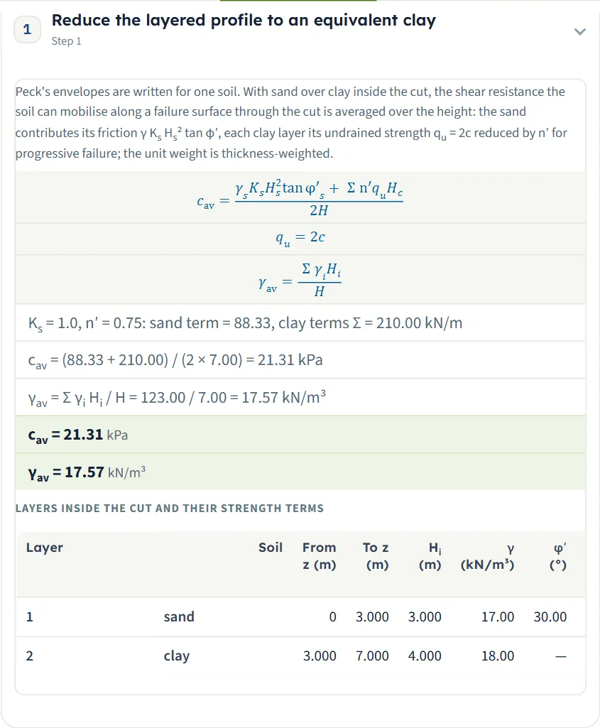
The equivalent clay is the average of the shear resistance the soil can mobilise through the cut. With Hs the thickness of the sand inside the cut, Ks its lateral pressure coefficient, φ′ its friction angle, Hc the thickness of a clay layer, qu = 2cu and n′ the progressive-failure coefficient:
With γav H/cav above 4 the cut is a soft-to-medium clay: the pressure is zero at the surface, grows to the full value σa at a quarter of the depth and stays there to the base, with σa = γav H − 4cav but not less than 0.3γav H. At or below 4 the clay is stiff: zero at the surface, rising over the top quarter, constant over the middle half and tapering to zero over the bottom quarter (a resultant of 0.75 σaH, against 0.875 σaH for the soft-to-medium shape), with σa = k γav H, k = 0.2 to 0.4 (0.3 by default). The module draws the envelope, solves the struts for any number of levels from 2 to 15 and gives the section modulus the sheeting and the wales need.
What you can describe
- Soil layers: up to ten, sand layers first, clay layers below; the bottom layer runs on below the base.
- Groundwater: below the base, or present at a depth zw.
- The cut: depth H, width B, plan length L, wall embedment d and, if there is one, the depth T from the base to a hard stratum.
- A uniform surcharge beside the cut.
- Struts: 2 to 15 levels, each by its depth, and one horizontal spacing s.
- Three steel members: the sheeting by its section modulus, the wale and the strut by their numbers or from the catalogue, each with a steel grade.
- Design code: EN 1993-1-1, or AISC 360-22 by LRFD or ASD.
Which module for which cut
- Sand from top to bottom, with the piping check of a dewatered cut: Braced cut in sand.
- Clay from top to bottom: Braced cut in clay.
- Sand over clay with the cut reaching the clay: this module. If the sand reaches the base, or the profile has no sand or no clay, the module stops and names the neighbouring module; see Messages.
- A wall that is not strutted but held by its embedment and anchors is a sheet-pile wall. A load beside the cut other than a uniform one is worked out in the Surcharge loads manuals.
Before you start: what you need
| What | Where from, and notes |
|---|---|
| The soil profile | Boring logs. Per layer, top down: sand or clay, thickness (not the last layer), unit weight, saturated unit weight; for sand the friction angle φ′, for clay the undrained cohesion cu. |
| The cut | Your design: depth H, width B, plan length L (optional), the embedment d of the wall below the base and the depth T to a hard stratum, if one is known. |
| The bracing | Your design: the depth of every strut and the horizontal spacing s. |
| The steel | The grade and the section properties of the sheeting (modulus per metre of wall), the wale (modulus, or a catalogue section) and the strut (area and weak-axis second moment of area, or a catalogue section). |
Quick start in eight steps
- Open the module and choose the units
Open Sand over clay from the Braced Cuts family. Pick SI · kN, SI · tf or US in the header; you can change it at any time.
- Enter the soil layers
In Soil layers choose Sand or Clay in the New layer form, fill it and press + Add layer, from the top down. Layers are added at the bottom, so enter sand first, then clay; to get a second sand above the clay, edit the type of an existing row. The last layer has no thickness.
- Set the water and the cut
In Groundwater choose Below the base or Present; in Cut geometry type H, B, d and, if known, T. Add a surcharge in Surcharge if there is one.
- Place the struts
In Struts type the horizontal spacing s and the depth of every strut, or drag the struts on the drawing; + Add a strut level adds one.
- Describe the steel
In Sections choose the grade of the sheeting, the wale and the strut and give their sections; in Analysis settings choose the code.
- Press Analyze
Press Analyze in the bar at the foot of the Model tab. The bar reads Analysed and the model locks. The module stays on the Model tab; the toast says “Analysed — see the Results tab and the Calculations.”
- Read the answer
Open Results: the half section, the strut loads, the wales, the values step by step, the tables and, last, the cards.
- Take the working and the report
The Calculations tab writes out the steps with your numbers; the Report tab saves a PDF or a Word file.
The screen: section and 3D
The layout is the one every GeoTerva module shares, described in the workspace guide. The drawing has two views, chosen above it:
- Section is the cut with its layers, the sheeting, the struts and wales, the apparent-pressure envelope and the dimensions. Before Analyze it follows your inputs; after Analyze it writes the load of every strut and Mmax , green where the member carries its force and red where it does not.
- 3D is an oblique view of the excavation: the sheeting on both sides, the wales and the struts at their spacing, the layers on the front face. After Analyze each strut level carries its load.
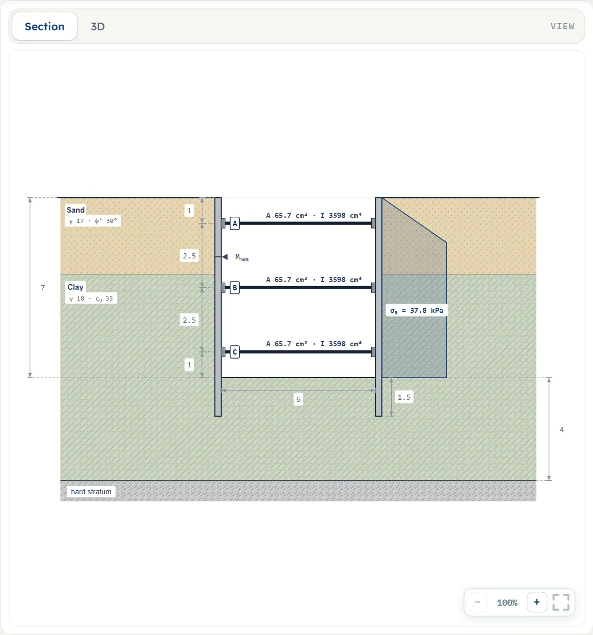
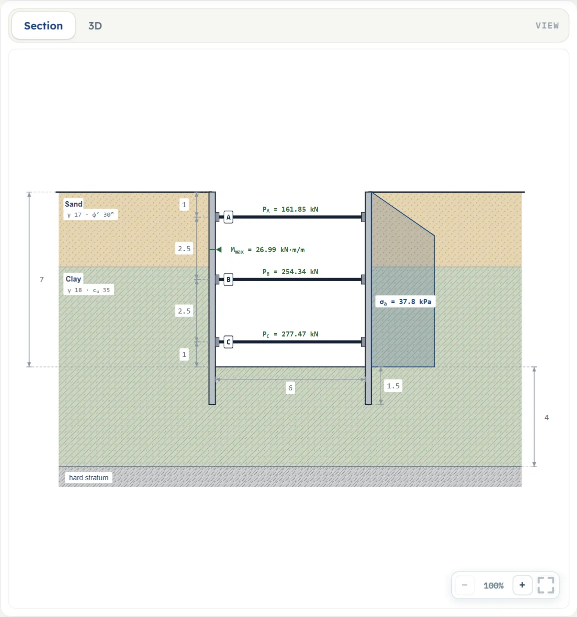
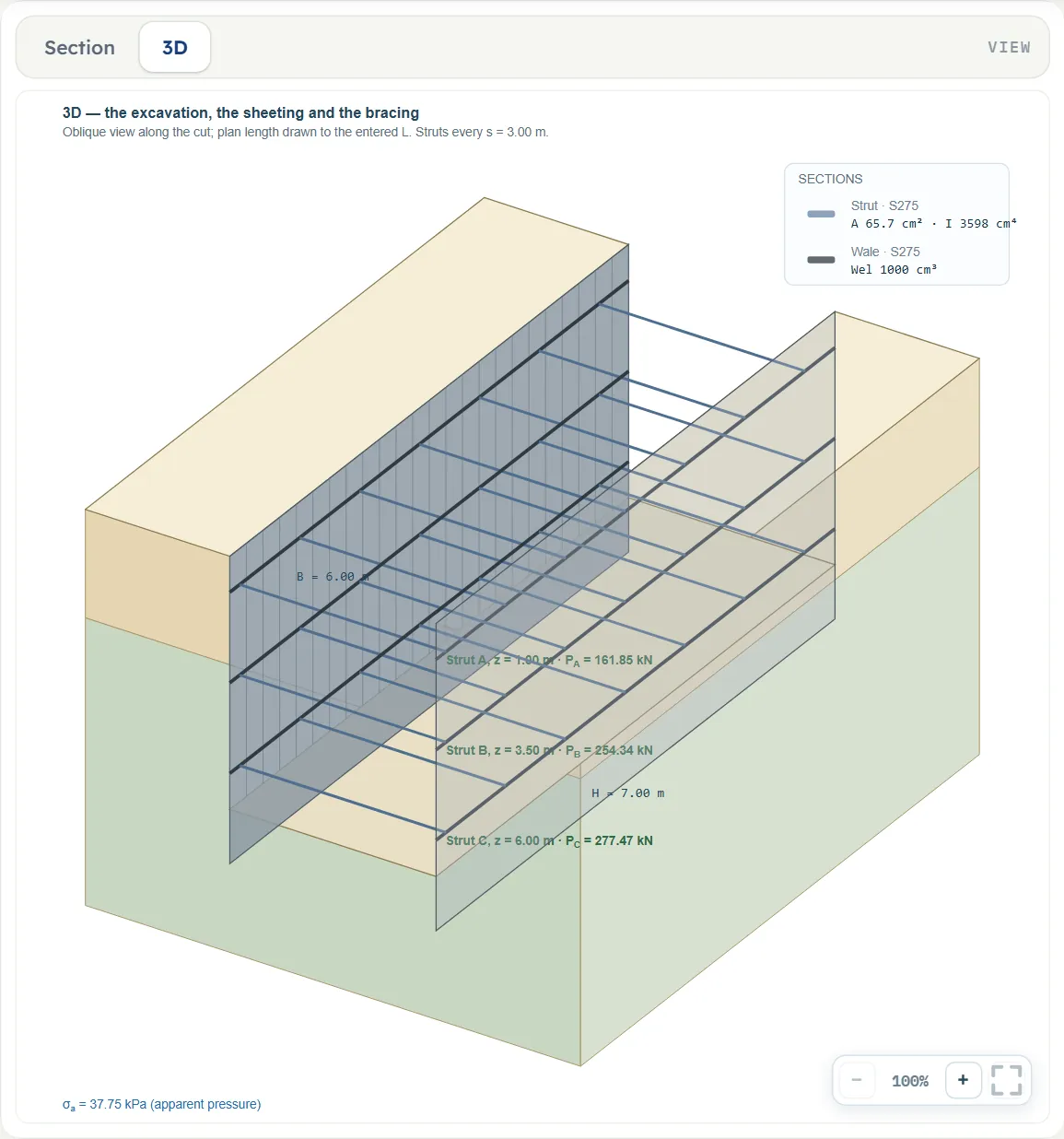
Dragging, and what is locked
Before Analyze two kinds of handle move inputs on the Section drawing (the cursor turns to a vertical double arrow); they move in steps of 5 cm and the Model tab follows:
- A strut moves up and down and changes its depth. The drag stops at 0.1 m below the surface and at 0.1 m above the base (H − 0.1 m); a depth typed outside the cut makes the analysis stop with the message “lies outside the cut”.
- The boundary between two layers moves up and down and changes the thickness of the layer above it (at least 0.1 m).
Nothing else is dragged: the depth H, the width and the water level are typed. After Analyze the handles are gone and nothing on the drawing can be moved. Each view has −, a percentage and + at the lower right and a button that fits the whole drawing in the pane. Before Analyze, pressing a layer on the drawing opens it in its form. There are no Show chips on the drawing.
Entering the model, section by section
The Model tab is an accordion of nine sections: Model data, Soil layers, Groundwater, Cut geometry, Surcharge, Struts, Sections, Base heave and Analysis settings. Model data opens independently of the others; Model data and Soil layers are open when the page loads, and opening any other section closes the previous one. The sections have Back and Next buttons at their foot: Soil layers only Next, Analysis settings only Back, Model data none. Units follow the preset in the header (m, kN, kPa, kN/m³ for SI · kN; the section moduli stay in cm³). After a switch the Section view converts, but the 3D view keeps m, kPa and cm³ in its labels while its strut loads follow the unit; in SI · tf the cohesion is in kg/cm² and in US the sheeting modulus is in in³/ft.
Model data
Save to file…, Open file…, Quick Save…, Load, Delete and Reset to defaults, with the two lines quoted under Before you start. Typed values are not kept after a reload.
Soil layers
The New layer form takes one layer at a time: its name (optional), the Sand or Clay button and the numbers that soil uses. + Add layer puts the form’s values into a new row of the table below it; the counter reads, for the example, “2 of 10”. Press a row (or its layer on the drawing) to edit it in the form; × takes it away. + Add layer appends at the bottom: the previous bottom layer takes its own stored thickness (adding to the default model makes the clay 12 m) and the new bottom row shows a dash. To get a second sand above the clay, edit the type of an existing row. The × buttons are disabled while two layers remain and work while more than two remain (the minimum is two). The form opens with Thickness 5, γ 18, γsat 19, cu 35 (Clay), and with Sand pressed 5, 18, 19, φ′ 30. The default model’s first layer is 3 m of sand (17, 20, 30); its second is a clay (18, 19, 35) with no thickness.
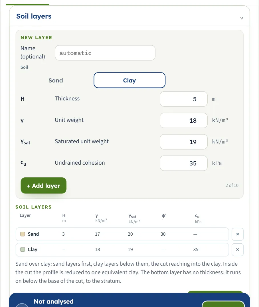
| Field | Default | What to enter |
|---|---|---|
| Name — | automatic | Optional. Empty gives Sand, Clay, or Sand-1, Sand-2 … when the profile has several of one soil. |
| Thickness H m · ft | 5 (form); 3 (first row) | The bottom layer has none: its row shows a dash, “it runs on below the base of the cut, to the stratum”. |
| Unit weight γ kN/m³ | 18 (form); 17 (first row) | Above the water table. |
| Saturated unit weight γsat kN/m³ | 19 (form); 20 (first row) | Below the water table, when the groundwater is present. |
| Friction angle φ′ ° | 30 (Sand in the form) | Sand only; clay shows a dash. |
| Undrained cohesion cu kPa | 35 (form) | Clay only; it must be above zero. |
Sand above, clay below: a sand layer under a clay layer stops the analysis. The profile is reduced to cav and γav over the depth H of the cut only; whatever lies below the base enters the bottom-heave check.
Groundwater
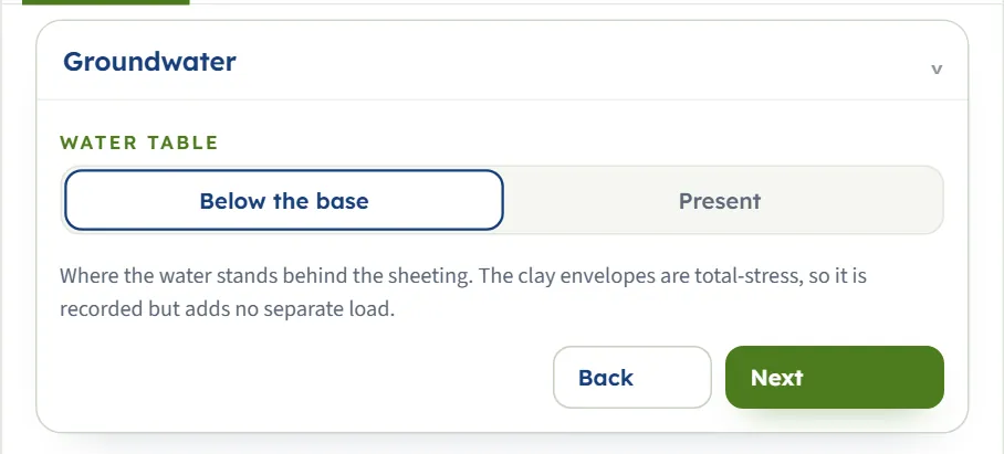
Below the base or Present; with Present a field asks for the depth of the water table zw (3 m by default). The module says: “The clay envelopes are total-stress, so it is recorded but adds no separate load.” Water changes the answer only through the unit weight: below the table the soil is taken at γsat . With the table at 2 m the example’s σa goes from 37.75 to 44.75 kPa.
Cut geometry
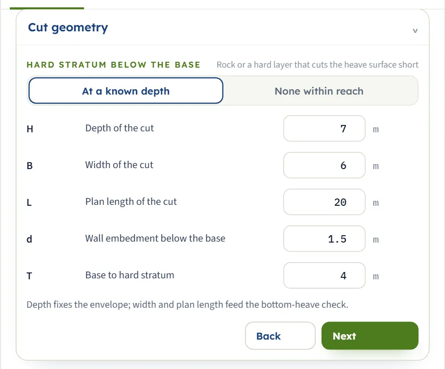
When the cut is wide and the stratum is near, T governs the heave surface: with B = 12 m the factor is the same 1.830 as with 6 m, because B′ = T = 4 m in both.
| Field | Default | What to enter |
|---|---|---|
| Depth of the cut H m · ft | 7 | The depth fixes the envelope. Must be above zero. |
| Width of the cut B m · ft | 6 | Feeds the bottom-heave check. |
| Plan length L m · ft | optional (20) | Feeds the heave check; empty is treated as an infinite length. |
| Wall embedment d m · ft | 1.5 | Drawn; the heave check does not credit it. |
| Base to hard stratum T m · ft | 4 | Shown when the choice is At a known depth; None within reach hides it. |
Surcharge
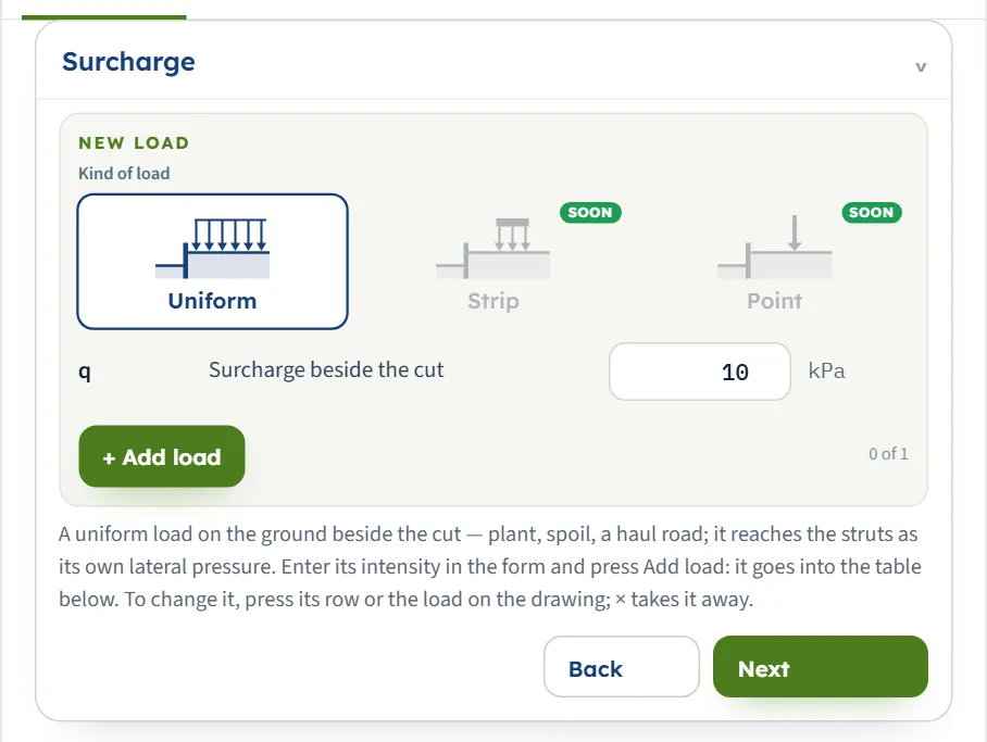
A uniform load on the ground beside the cut, entered as in the sheet-pile modules: the New load form holds the intensity q (10 kPa in the form), + Add load puts it in the table (the counter reads “0 of 1” until you do), × takes it away. The Strip and Point buttons are marked SOON and cannot be pressed. The load reaches the struts as a uniform lateral pressure over the full height and also enters the heave check: in the example q = 20 kPa raises the largest strut load from 277.5 to 424.5 kN and lowers the heave factor from 1.830 to 1.574.
Struts
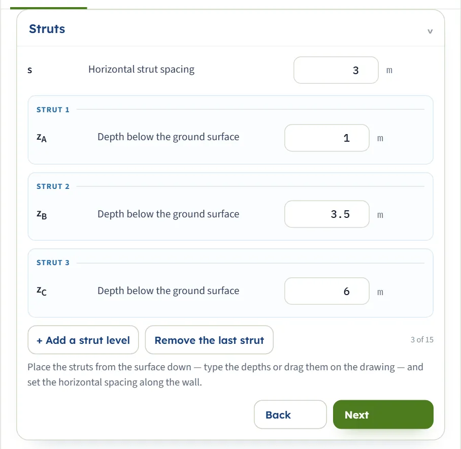
+ Add a strut level adds one (up to 15); Remove the last strut takes the last away. At least two levels are needed. Every strut must lie strictly between the surface and the base. Type the depths or drag the struts.
| Field | Default | What to enter |
|---|---|---|
| Horizontal strut spacing s m · ft | 3 | Centre to centre along the wall; the load of a strut is P = R × s. |
| Depth of strut A, B, C … zA m · ft | 1, 3.5, 6 | Below the ground surface, from the top down. |
Sections
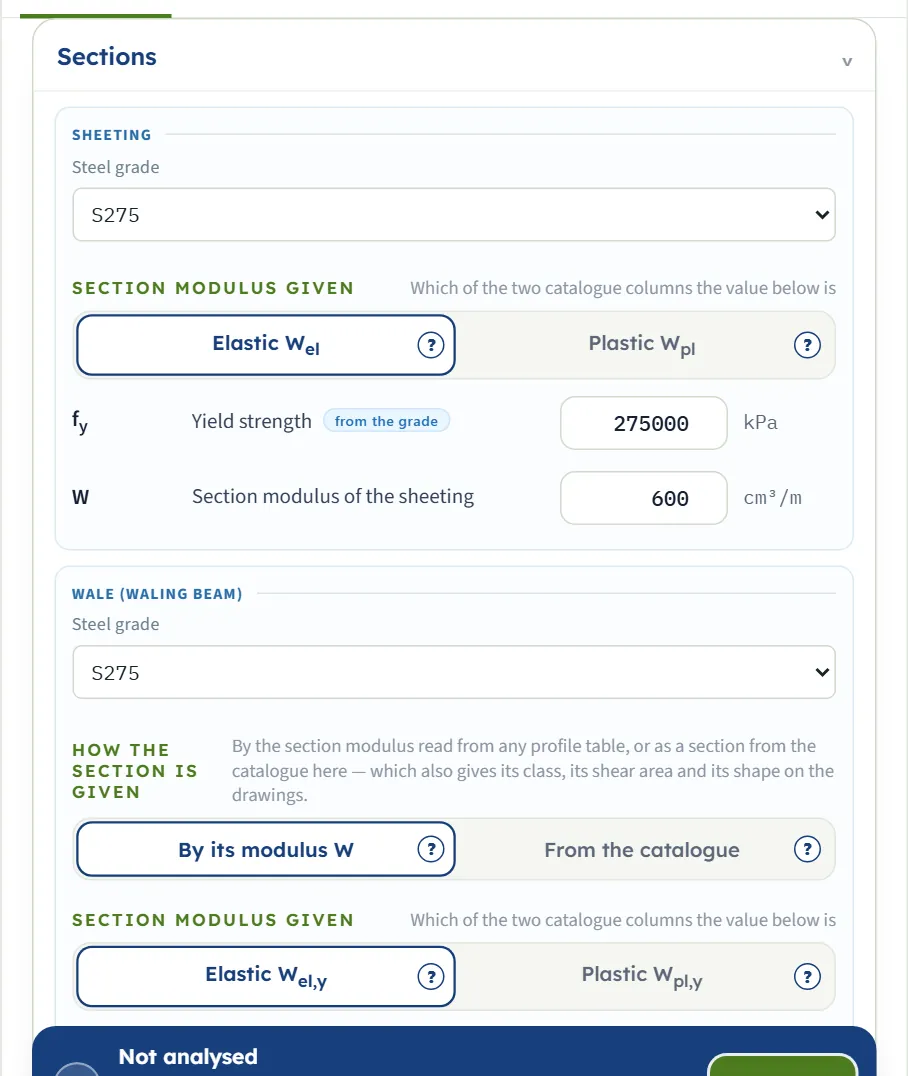
Three members, each a steel grade and a section. S235, S275, S355 or Typed sets the yield strength fy: the box follows the grade (275 000 kPa for S275) and may be typed over; clearing it hands it back. In the example all three are S275.
- Sheeting: the section modulus per metre of wall (default 600 cm³/m) and which column of the catalogue it is, Elastic Wel or Plastic Wpl.
- Wale (waling beam): By its modulus W (default 1 000 cm³, elastic or plastic) or From the catalogue, which also gives its class, its shear area and its shape on the drawings.
- Strut: By A and I (default A = 65.7 cm², weak-axis second moment of area 3 598 cm⁴, buckling curve) or From the catalogue; the buckling length Lb follows the width of the cut and the effective length factor K is 1; the modulus of elasticity follows the code (210 000 000 kPa for EN 1993-1-1, 200 000 000 for AISC 360-22).
Base heave
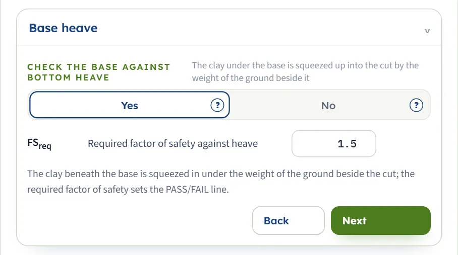
Yes or No, and the required factor of safety (1.5), which sets the PASS or FAIL line of the heave card. With No the heave factor is not calculated.
Analysis settings
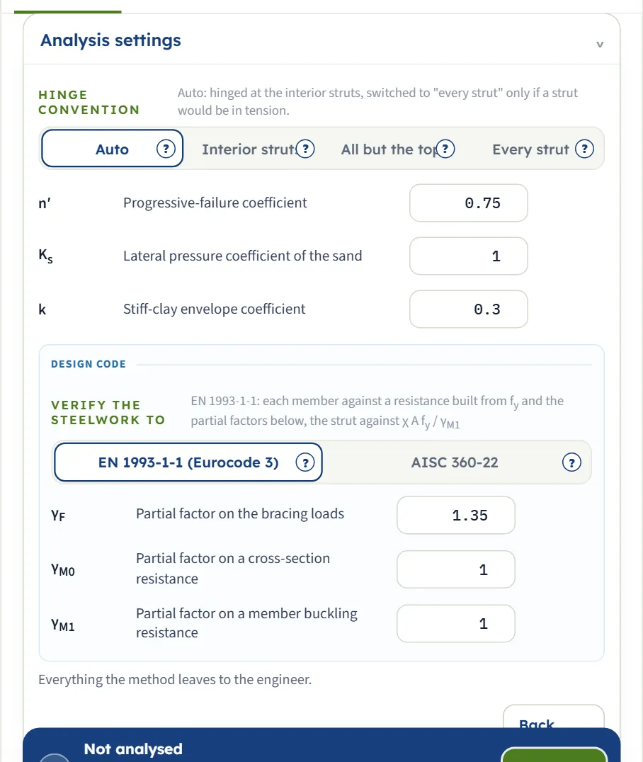
| Field | Default | What to enter |
|---|---|---|
| Progressive-failure coefficient n′ — | 0.75 | Reduces the clay’s qu in cav . |
| Lateral pressure coefficient of the sand Ks — | 1 | The sand term of cav is proportional to it. |
| Stiff-clay envelope coefficient k — | 0.3 | Used when γav H/cav is 4 or less; the module keeps it between 0.2 and 0.4. |
| Partial factor on the bracing loads γF — | 1.35 | EN 1993-1-1. With AISC 360-22 the field is the load factor γH, 1.6. |
| Partial factors on resistance γM0, γM1 — | 1, 1 | Cross-section and member buckling resistance (EN 1993-1-1). |
The module keeps the values within these ranges: n′ 0.5 to 1, Ks 0.1 to 2, k 0.2 to 0.4 (clamped), γF 1 to 1.6, γM0 and γM1 1 to 1.3, γH 1 to 2, the required heave factor 1 to 3; up to 10 layers, 2 to 15 struts, a strut depth of at least 0.1 m.
Two more choices sit here: the hinge convention and the design code, EN 1993-1-1 (Eurocode 3) or AISC 360-22 with LRFD or ASD.
Choosing the method: the envelope and the hinges
The envelope is chosen for you
You do not pick the envelope: the stability number does. In the example cav = 21.31 kPa and γav = 17.57 kN/m³, so γav H/cav = 5.77, above 4: the soft-to-medium envelope, with σa = 37.75 kPa. When the number lies close to 4 the module adds a note: with cu = 60 kPa it is 3.84 and the stiff envelope gives σa = 36.90 kPa, and the note warns that the other branch would give a resultant a sixth larger, so that where cav is uncertain you should run both and design for the heavier.
Two things keep the result from running away. First, the floor of 0.3γav H in the soft-to-medium formula: with φ′ = 36° the formula gives less, the floor governs and σa is 36.90 kPa, the same as with n′ = 1.0. Second, Ks and n′ move cav only through the sand term and the clay term; Ks = 0.5 raises σa to 50.39 kPa because less sand strength is credited.
The hinge convention
- Auto (default): the sheeting is hinged at every strut except the top and bottom ones, and the module switches to every strut hinged when that layout would put a strut in tension. It adds the note “Hinge convention switched automatically: hinged at the interior struts this layout would put strut X in tension (R = …), so the sheeting is treated as hinged at every strut instead” and, for a strut that stays slack, the warning “Strut X at z = … would be in tension in this layout — it is slack and carries nothing”.
- Interior struts: hinged at every strut except the top and bottom ones. The example solves as two pieces, 0 to 3.5 m on struts A and B and 3.5 to 7 m on B and C.
- All but the top and Every strut: hinged at more levels. With every strut hinged the example’s largest strut load is 281.3 kN and Mmax 29.49 kN·m/m, against 277.5 kN and 26.99 kN·m/m.
The design code
EN 1993-1-1 multiplies the working values by γF and verifies the sheeting and the wales in bending and the struts in compression and flexural buckling; AISC 360-22 by LRFD (load factor γH = 1.6, φ = 0.90) or ASD (Ω = 1.67). For the example, AISC by LRFD gives the section modulus the sheeting needs as 174.5 cm³/m and the utilisations 0.2908, 0.6727 and 0.3933 for the sheeting, the wale and the strut.
Analyze and read the results
Press Analyze. The module stays on the Model tab and the bar changes to Analysed — the braced cut calculated, with Notes (5) and Edit inputs; when a run carries warnings, the Warnings window opens by itself; close it and the bar keeps “— 1 warning” and a Warnings button to open it again. The answer is on the Results tab, in this order:
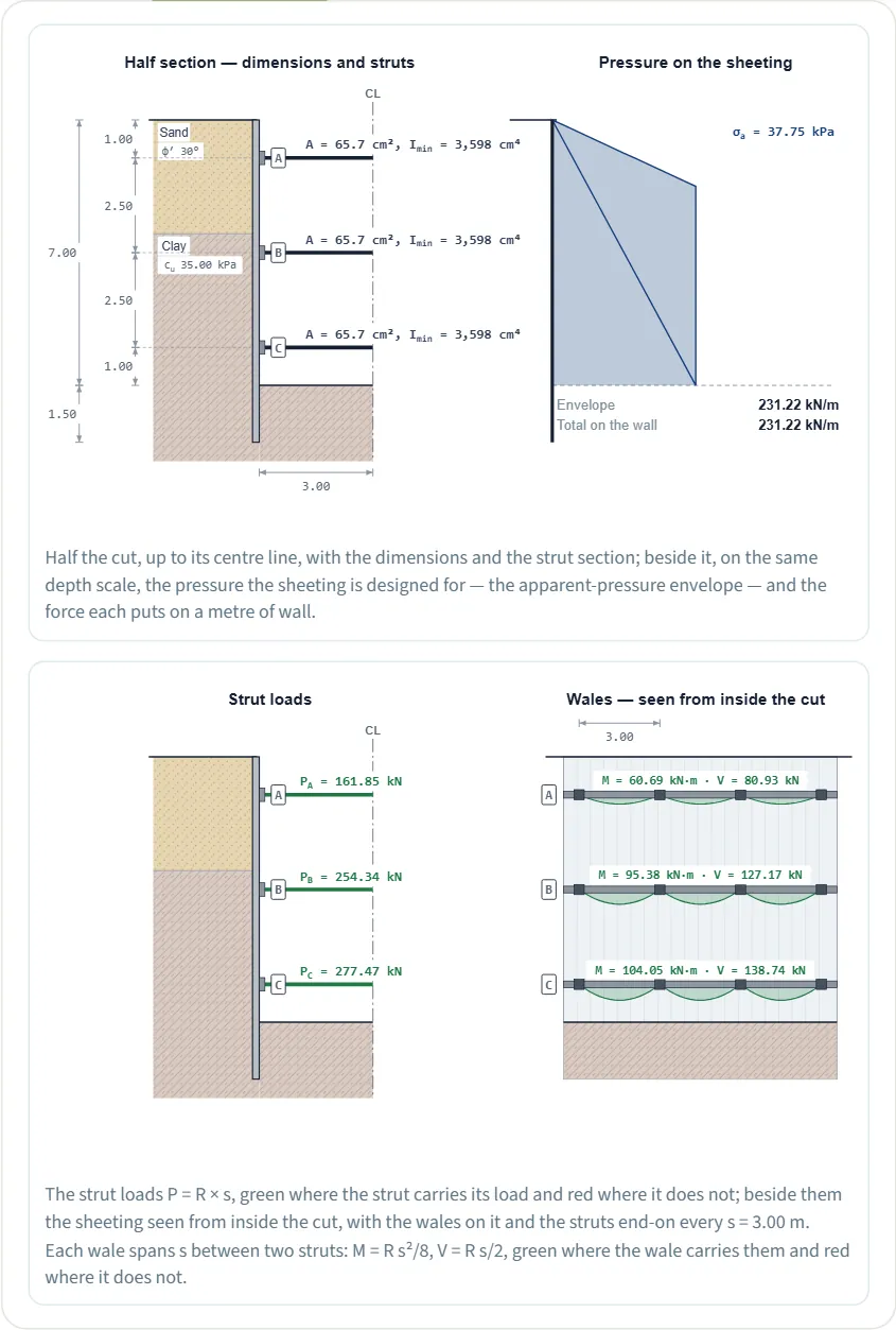
- The half section with the dimensions and the strut sections, and the pressure on the sheeting with σa, the area of the envelope and the force it puts on a metre of wall (231.22 kN/m in the example).
- The strut loads PA, PB, PC and the wales seen from inside the cut, with M = Rs²/8 and V = Rs/2 for each level, green where the member carries them and red where it does not.
- Values, step by step, then the tables: the layers inside the cut and their strength terms, the beam pieces of the wall, the strut loads and the wales level by level.
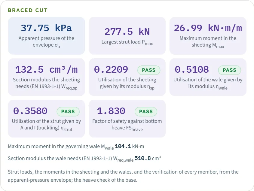
- The cards: σa, Pmax , Mmax , Wreq,sp , the utilisations ηsp , ηwale and ηstrut , and the heave factor FSheave (eight cards); under them, in plain lines, the moment and the modulus of the governing wale.
The verdict words
Each utilisation and the heave factor carries PASS or FAIL; a utilisation close to 1 reads PASS — near capacity (the wale at cu = 15 kPa, 0.9747). A utilisation is the demand over the resistance, so below 1 passes; the heave factor passes when it reaches the required one: 1.830 is a PASS against 1.5 and a FAIL against 2.0.

The Calculations tab, the report and the Theory tab
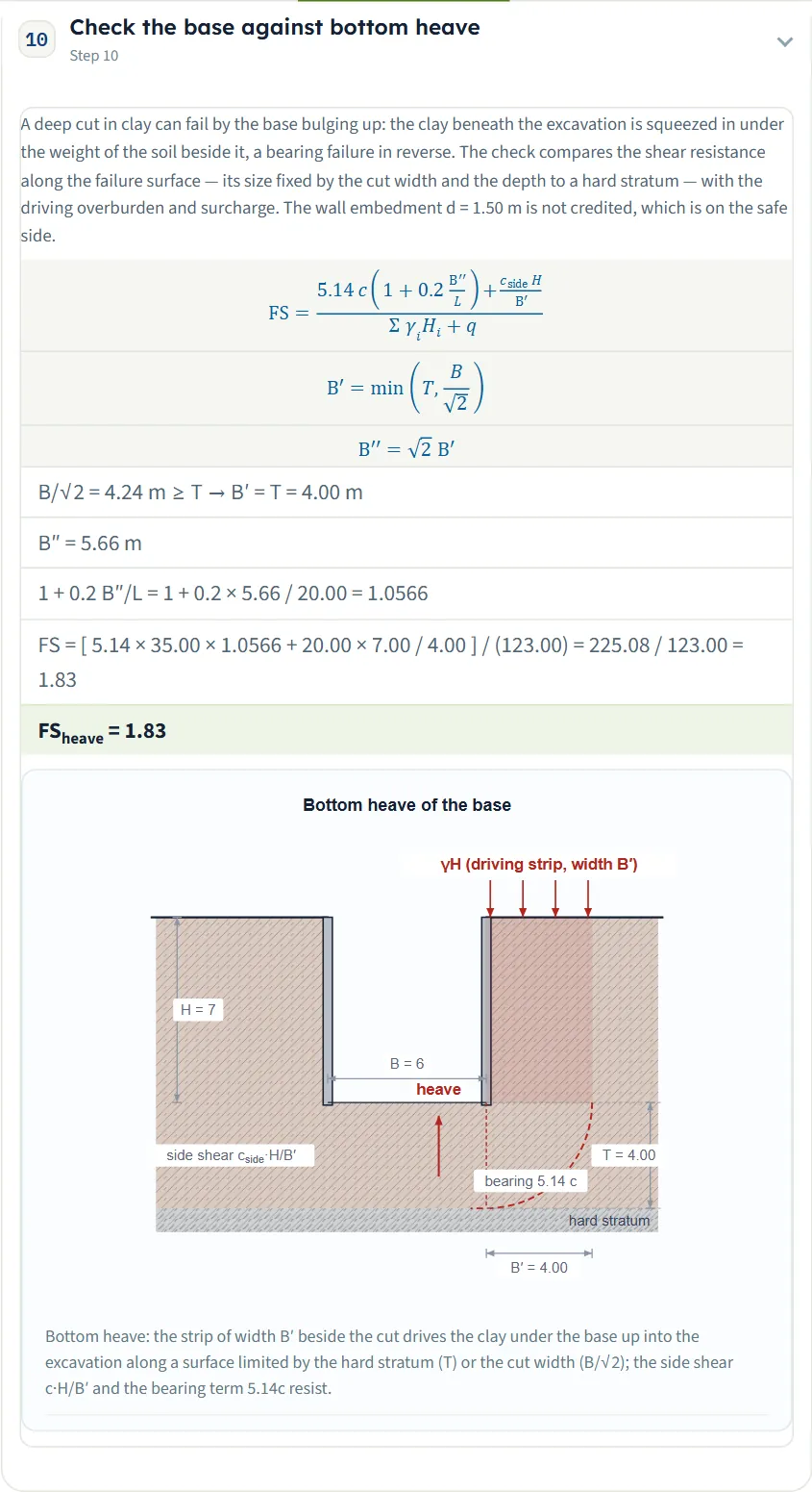
Calculations writes the working of the 17 steps of the example with your numbers: the reduction to the equivalent clay (step 1), the choice of the envelope (2), the idealisation of the sheeting and the reactions (3), a step for every piece of the wall (4 and 5), the strength of the members (6), the strut loads (7), the moments in the sheeting and the wales (8 and 9), the bottom heave (10), the design actions (11) and the verification of the sheeting, the wale and the strut (12 to 17). A step opens and closes by its header.
Report has a cover with Project, Location, Client, Report no., Date, Prepared by, Title / qualification, Checked by and Notes (printed only when filled in; the cover details are kept in this browser and saved with the model file). Save as PDF and Download Word (.docx) produce the summary report: a cover and a solution summary, then seven parts: introduction and scope, input data, calculation, results, assumptions and notes, summary, references, with the drawings. The cover says that the warnings appear in its Warnings and notes section.

Theory has 17 sections: the braced cut and its members; why the pressure is not Rankine’s; apparent pressure from measured strut loads; the envelopes for clay; sand and clay in one cut; a surcharge, and water in clay; struts; sheet piles; wales; the members as they are given; verifying the steel to EN 1993-1-1 and to AISC 360-22; the envelopes against real cuts; the base of a cut in clay; what the method assumes; a worked example; and references.
Worked example: the default cut, by hand
The default model: 3 m of sand (γ = 17, φ′ = 30°) over clay (γ = 18, cu = 35), H = 7 m, B = 6 m, L = 20 m, T = 4 m, struts at 1, 3.5 and 6 m, s = 3 m, Ks = 1, n′ = 0.75, S275 steel, EN 1993-1-1, γF = 1.35. Every figure below is on the Calculations tab and was recomputed independently.
1 The equivalent clay
2 The envelope
3 The strut loads
The sheeting is hinged at B, so there are two pieces. Piece 1 (0 to 3.5 m) carries W = 99.09 kN/m acting at 2.139 m: RB = 99.09 × (2.139 − 1.00) / 2.50 = 45.14 and RA = 53.95 kN/m. Piece 2 (3.5 to 7 m) carries 132.13 kN/m acting at 5.25 m: RC = 132.13 × (5.25 − 3.50) / 2.50 = 92.49 and its share of B is 39.64. The total on B is 84.78 kN/m, and the loads P = R × 3 are:
| Strut | R (kN/m) | P (kN) |
|---|---|---|
| A at 1.0 m | 53.95 | 161.9 |
| B at 3.5 m | 84.78 | 254.3 |
| C at 6.0 m | 92.49 | 277.5 |
4 Sheeting, wale and strut
The largest moment in the sheeting is Mmax = 26.99 kN·m/m, at 2.30 m in piece 1. The design moment is 1.35 × 26.99 = 36.44 kN·m/m, so Wreq = 36.44 / 275 000 = 132.5 cm³/m; the 600 cm³/m given resists 165.00 kN·m/m, a utilisation of 0.2209. The wale at level C spans 3 m: M = 92.49 × 3² / 8 = 104.05 kN·m, design 140.47, needing 510.8 cm³ against the 1 000 given: 0.5108. The strut takes NEd = 1.35 × 277.47 = 374.58 kN; with λ̄ = 0.9339 and χ = 0.5791 its buckling resistance is 1 046.36 kN: 0.3580.
5 The base
Here 20.00 kPa is the clay’s strength averaged over the height of the cut with sand counted as zero, and 123.00 kPa is ΣγiHi. The same cut in the other unit systems gives slightly different figures, because the module rounds the equivalent unit weight and cohesion to the decimals of the chosen unit before it builds the envelope (17.57 kN/m³, 1.79 t/m³): SI · tf σa = 3.840 t/m², Pmax = 28.23 tf, Mmax = 2.746 tf·m/m and FS 1.825; US σa = 0.7887 ksf, Pmax = 62.40 kip, Mmax = 6.071 kip·ft/ft and FS 1.829; SI · kN FS 1.830. The differences stay within 0.3 %.
How each input changes the answer
Each row changes one value of the default example and reads the module: σa and the largest strut load Pmax ; then the heave factor FS and the utilisation of the wale ηwale . The default gives 37.75 kPa and 277.5 kN; 1.830 and 0.5108. The unit weight is 17 kN/m³ in the sand and 18 kN/m³ in the clay, the saturated unit weight 20 and 19 kN/m³, unless the row changes it; the row for the 10 m cut changes H and the struts.
| Change | σa · Pmax | FS · wale η |
|---|---|---|
| Sand thickness 3 → 1.5 m | 37.36 kPa · 274.6 kN | 1.913 · 0.5055 |
| Sand thickness 3 → 5 m | 36.31 kPa · 266.9 kN | 1.716 · 0.4913 |
| Sand φ′ 30° → 36° | 36.90 kPa · 271.2 kN | 1.830 · 0.4993 |
| Ks 1 → 0.5 | 50.39 kPa · 370.4 kN | 1.830 · 0.6818 |
| n′ 0.75 → 1.0 | 36.90 kPa · 271.2 kN | 1.830 · 0.4993 |
| Clay cu 35 → 60 kPa | 36.90 kPa · 264.8 kN | 3.137 · 0.4874 |
| Clay cu 35 → 15 kPa | 72.03 kPa · 529.4 kN | 0.7842 FAIL · 0.9747 |
| Clay γ 18 → 20 kN/m³ (γsat stays 19) | 45.73 kPa · 336.1 kN | 1.718 · 0.6188 |
| Spacing s 3 → 4 m | 37.75 kPa · 370.0 kN | 1.830 · 0.9081 |
| Surcharge 20 kPa | 37.75 kPa · 424.5 kN | 1.574 · 0.7814 |
| Water table at 2 m | 44.75 kPa · 328.9 kN | 1.731 · 0.6055 |
| Width B 6 → 3 m | 37.75 kPa · 277.5 kN | 2.043 · 0.5108 |
| Width B 6 → 12 m | 37.75 kPa · 277.5 kN | 1.830 · 0.5108 |
| No hard stratum | 37.75 kPa · 277.5 kN | 1.819 · 0.5108 |
| Every strut hinged | 37.75 kPa · 281.3 kN | 1.830 · 0.5179 |
| Required FS 1.5 → 2.0 | 37.75 kPa · 277.5 kN | 1.830 FAIL · 0.5108 |
| Cut 10 m deep, struts at 1, 3.5, 6, 8.5 m | 85.84 kPa · 824.1 kN | 1.42 FAIL · 1.517 FAIL |
What the rows show:
- The sand enters through the average and the floor. With 1.5 m or 5 m of sand the 0.3γav H floor governs, so σa follows the average unit weight (37.36 and 36.31 kPa against 37.75); a stronger sand (φ′ = 36°) changes nothing in the pressure beyond the floor, 36.90 kPa, the same as with n′ = 1.0.
- cu acts twice. A stronger clay (cu = 60 kPa) leaves σa at the stiff-envelope value and raises the heave factor from 1.830 to 3.137; a weaker clay (15 kPa) lifts σa to 72.03 kPa and drops the factor to 0.7842, a FAIL.
- The spacing scales the loads. s = 4 m multiplies every strut load by 4/3 (277.5 to 370.0 kN) and the wale moment by 16/9: the wale utilisation goes from 0.5108 to 0.9081. The pressure and the heave factor do not move.
- The width acts only while it governs. Narrowing the cut to 3 m raises the heave factor to 2.043; widening it to 12 m changes nothing, because the stratum 4 m below the base already limits the failure surface. Without a stratum the cut’s width alone limits it and the factor falls to 1.819.
- A deeper cut raises the pressure and every load and lowers the heave factor. At 10 m with a fourth strut the pressure is 85.84 kPa, the largest strut 824.1 kN, the wale and the strut fail (1.517 and 1.063) and the heave factor falls from 1.830 to 1.42.
Messages
Stops
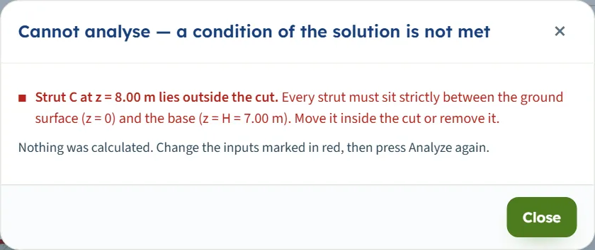
A stop appears in a dialog headed “Cannot analyse — a condition of the solution is not met”, followed by the reason, the instruction, and “Nothing was calculated. Change the inputs marked in red, then press Analyze again.” The stops this module gives:
- “Strut C at z = 8.00 m lies outside the cut. Every strut must sit strictly between the ground surface (z = 0) and the base (z = H = 7.00 m). Move it inside the cut or remove it.”
- “The cut does not reach the clay (sand 8.00 m ≥ H). With only sand inside the cut the equivalent-clay average has no clay term; the sand module applies. Deepen the cut, thin the sand, or open the sand module.”
- “A sand layer lies below a clay layer. The source gives the equivalent-clay rule for sand OVER clay only; clay over sand has no published envelope. Reorder the layers (sand first), or model the cut with the sand or the clay module.”
- “No sand layer in the profile. This module is for sand over clay; an all-clay profile belongs to the clay module. Add the sand layer above the clay, or open the clay module.”
- “No clay layer in the profile. This module is for sand over clay; an all-sand profile belongs to the sand module. Add the clay layer, or open the sand module.”
- An empty box: the dialog reads “Cannot analyse — 2 input errors” and lists, for example, “Depth below the ground surface (zB) is missing.”
The module also stops for a cut depth, unit weight, friction angle, cohesion, strut spacing or yield strength that is not above zero, for fewer than two struts and for two struts at one depth.
Warnings
A warning does not stop the analysis; the Warnings window opens by itself right after Analyze; close it and the bar keeps “— 1 warning” (or “— 3 warnings”) with a Warnings button to open it again. Each warning has its triangle. In the cut 10 m deep (struts at 1, 3.5, 6 and 8.5 m) there are three:
- “Factor of safety against bottom heave FS = 1.42 is below the required 1.50.” followed by “The clay beneath the base cannot carry the overburden beside the cut with the intended margin. Extend the sheeting below the base, reduce the surcharge beside the cut, narrow the cut or improve the clay under the base.”
- “The wale given does not carry the design moment: MEd / Mc,Rd = 1.52.” with the resistance, the design moment and the modulus the wale asks for.
- “The strut section given does not carry the design load: NEd / Nb,Rd = 1.06.” with the buckling resistance, 1 046.36 kN, and the design load, 1 112.49 kN.

Notes
Notes list what the run assumed; the bar of the default example reads “Notes (5)”. Among the notes: “The stability number γavH/cav = 3.92 lies close to 4, where the two clay envelopes change over.” (a cut 4 m deep, with struts at 1, 2.5 and 3.5 m); “Cut depth H = 4.00 m is shallower than the ≈6 m the envelopes were derived for.” (the same cut); and, with the groundwater present, that the run is undrained and the clay envelope carries no separate hydrostatic pressure. A surcharge, the absence of a hard stratum and a switch to AISC 360-22 each add a note that says how the run was computed.
Good practice
- Put the sand first and give it its real thickness. Only the sand above the clay enters the reduction; the sand’s φ′ and Ks matter as long as the formula, not the floor, governs.
- Read the stability number. Close to 4 the module warns that the two envelopes differ by about a sixth; run the other branch as well and design for the heavier.
- Give the real strut depths. The reactions follow the hinged pieces, so a strut moved changes the others.
- Check all four verdicts. The sheeting, the wale, the strut and the base are separate cards; one FAIL is enough to change the design.
- Give the width and the stratum depth to have the heave check reflect the cut; leaving the stratum out is the safe side.
- Keep the model. The page opens on the default model; use Save to file… or Quick Save….
- Treat shallow cuts as preliminary. The envelopes were derived for cuts deeper than about 6 m; the module says so.
Frequently asked questions
How does the module treat sand over clay?
It reduces the profile inside the cut to one equivalent clay: cav = [γs Ks Hs² tan φ′ + Σ n′ qu Hc] / 2H and γav = ΣγiHi/H. The example gives 21.31 kPa and 17.57 kN/m³.
Which envelope is used?
The one the stability number γav H/cav picks: above 4 the soft-to-medium trapezoid with σa = γav H − 4cav , at least 0.3γav H; at or below 4 the stiff trapezoid with σa = kγav H. The example has 5.77 and 37.75 kPa.
How are the strut loads found?
The sheeting is cut into pieces at the hinges; each piece is a determinate beam on its struts, solved by moment and force equilibrium, and a strut at a hinge collects a reaction from both sides. P = R × s: 161.9, 254.3 and 277.5 kN in the example.
Why did the analysis stop with “lies outside the cut”?
A strut must lie strictly between the surface and the base. Dragging a strut below the base does that; move it back or remove it.
Why does the module say the sand reaches the base?
The cut must reach the clay. With only sand inside the cut the average has no clay term, so the module points to the sand module. Deepen the cut or thin the sand.
Does the water table load the wall?
No separate pressure is added: the clay envelopes are total-stress. Below the table the soil is taken at its saturated unit weight, which raises σa: 44.75 kPa instead of 37.75 with the table at 2 m.
What does the bottom-heave check use?
The clay under the base carries the bearing term 5.14c(1 + 0.2B″/L), the layers beside the cut give the side shear cside H/B′ (sand counted as zero) and the overburden ΣγiHi + q drives it. B′ is B/√2 or the depth T to the hard stratum if smaller; the example gives 1.83.
Why does a wider cut not change the heave factor?
When T is smaller than B/√2 the stratum limits the heave surface (B′ = T). With B = 12 m the factor is 1.830, as with 6 m; narrowing to 3 m raises it to 2.043.
Which codes does it check the steel to?
EN 1993-1-1 with γF, γM0 and γM1 , or AISC 360-22 by LRFD (γH = 1.6, φ = 0.90) or ASD (Ω = 1.67). The sheeting is checked on its modulus, the wale on its modulus or as a catalogue section, the strut in buckling.
Does the module remember my inputs?
No. It opens every time on the default model, not analysed; only the unit system is kept. Use Save to file or Quick Save to keep a model.
Can I drag things on the drawing?
Before Analyze, the struts and the boundary between layers. After Analyze nothing; press Edit inputs to unlock the model.
Which units does it use?
SI · kN, SI · tf or US, changed in the header at any time, even after Analyze. For the example: Mmax = 26.99 kN·m/m, 2.746 tf·m/m or 6.071 kip·ft/ft.