
On this page · 5 chapters
The vertical stress below a flexible line load of infinite length: its derivation from Boussinesq’s point load, the nondimensional form Δσz/(q/z), and several line loads by superposition. The figures are computed from the equations.
 PDF
Lecture slides
Ready-made slides for lectures and self-study
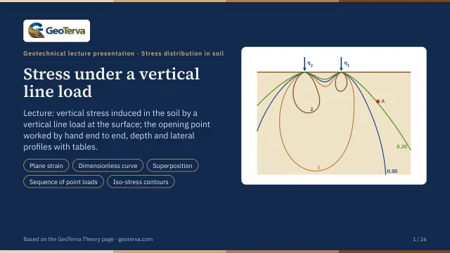
The mechanism, the derivation, the equations and the figures of this page, in teaching order. Every slide links back to its chapter.
1Scope and assumptionsA load per unit length along an infinite line.
A line load is a load q per unit length acting along a straight line of infinite length on the surface — a long wall, a rail, a strip so narrow that its width does not matter. Every cross section perpendicular to the line is loaded in the same way, so the stresses are those of plane strain: they depend only on the horizontal distance x from the line and on the depth z.
- The load is flexible, vertical and of infinite length along y.
- The soil is a homogeneous, isotropic, linearly elastic half-space, as in Boussinesq’s solution.
- Δσz is the increase caused by the load; the overburden pressure of the soil above the point is not included.
2The vertical stressFrom a row of point loads to Δσz = 2qz³/[π(x² + z²)²].
The line load can be seen as a row of point loads dP = q dy along y. Each gives the Boussinesq stress of the previous module, with r² = x² + y²; adding them all along the line,
and the integral has a closed value, 4/[3(x² + z²)²], which gives
Unlike a point load, the stress falls off only as 1/z along the axis of the load (x = 0): Δσz = 2q/(πz) = 0.637 q/z.
3The nondimensional formΔσz/(q/z) against x/z.
Dividing by z and writing x/z, the equation takes a nondimensional form, one curve for every line load:
| x/z | Δσz/(q/z) | x/z | Δσz/(q/z) |
|---|---|---|---|
| 0.0 | 0.637 | 0.1 | 0.624 |
| 0.2 | 0.589 | 0.3 | 0.536 |
| 0.4 | 0.473 | 0.5 | 0.407 |
| 0.6 | 0.344 | 0.7 | 0.287 |
| 0.8 | 0.237 | 0.9 | 0.194 |
| 1.0 | 0.159 | 1.2 | 0.107 |
| 1.4 | 0.073 | 1.6 | 0.050 |
| 1.8 | 0.035 | 2.0 | 0.025 |
| 2.4 | 0.014 | 2.8 | 0.008 |
| 3.0 | 0.006 | 3.5 | 0.004 |
4Several line loadsSuperposition, worked through.
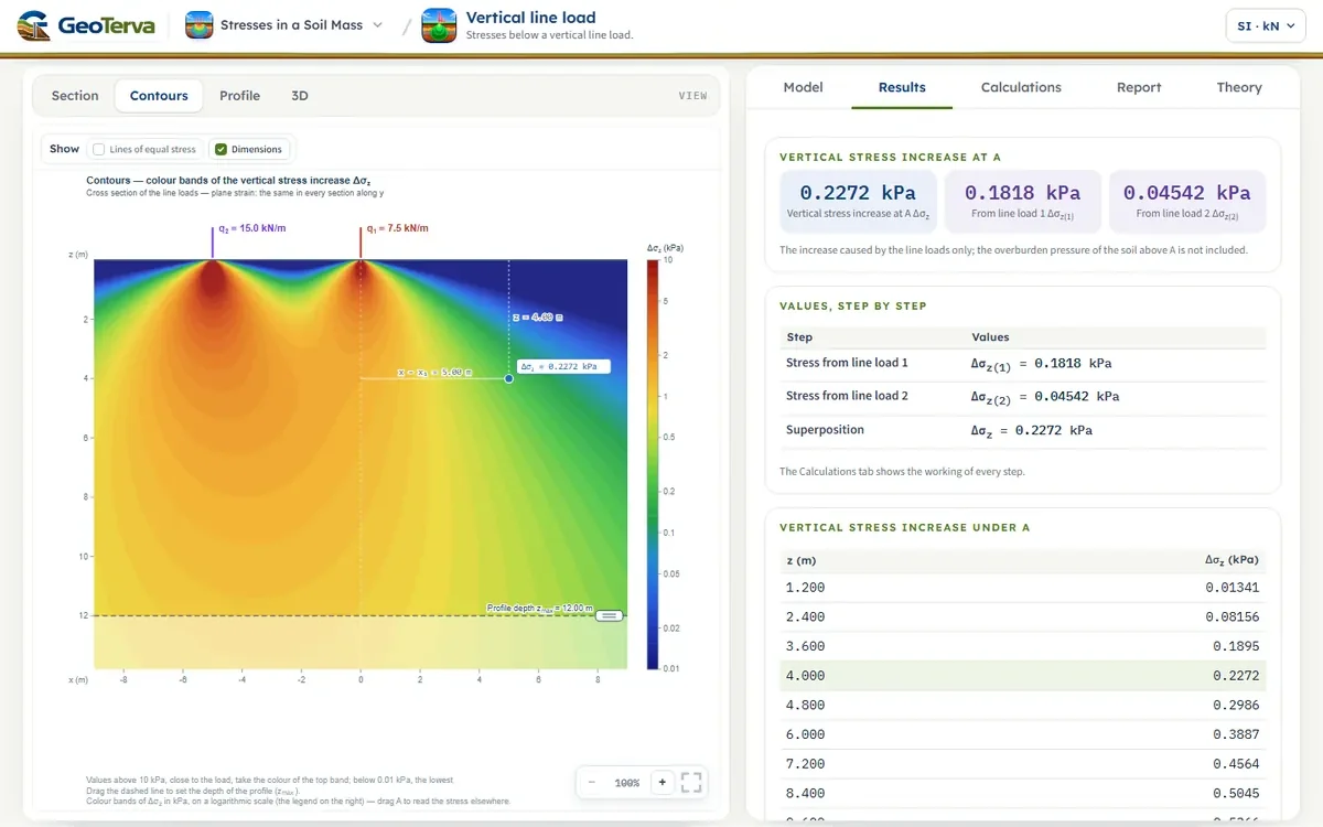
The soil is elastic, so the stresses of several loads add. For the two loads of the figure the stress at A is the sum of the stresses each would cause alone, each with its own horizontal distance to A:
The module takes up to eight parallel line loads, put in one by one with Add line load, each with its intensity and its position and no two at the same position; it opens with this example.
5ReferencesSources.
- Das, B.M. (2018). Principles of Geotechnical Engineering, 9th ed. Cengage Learning.
- Boussinesq, J. (1883). Application des Potentiels… Gauthier-Villars, Paris.
From theory to your own design
Find the stress below your own line loads in minutes
- The vertical stress increase at any point below one or several line loads
- The depth profile and the contours
- Drag a load or the point on the section
- A clean calculation report, saved as a PDF. Online: nothing to install, no dongle, on a phone, a tablet or a PC