
On this page · 5 chapters
The vertical stress below a long trapezoidal embankment: Osterberg's influence value and the equivalent sum of strip loads. The figures are computed from the equations.
 PDF
Lecture slides
Ready-made slides for lectures and self-study
The mechanism, the derivation, the equations and the figures of this page, in teaching order. Every slide links back to its chapter.
1Scope and assumptionsA trapezoidal fill.
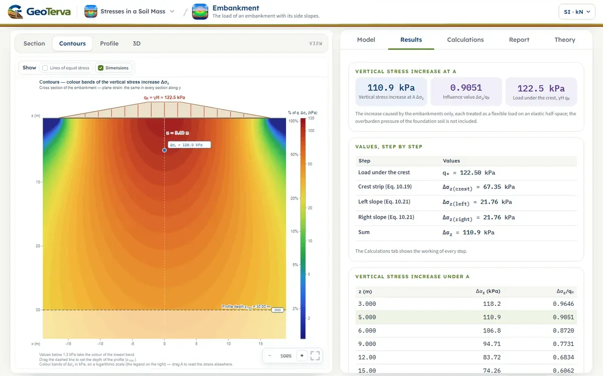
A road or railway embankment, a levee, a long stockpile — the load of a trapezoidal fill on the ground. Its weight per unit area is q0 = γH under the crest and falls linearly to zero at the toes. Like the strip loads it is long, so the problem is two-dimensional.
- The fill acts as a flexible load γ·(height) on the ground surface; its own stiffness is ignored.
- The foundation soil is a homogeneous, isotropic, linearly elastic half-space; plane strain.
- Δσz is the increase caused by the embankment only.
2Osterberg's solutionΔσz = q0 I2.
For the half embankment of the figure — the point A below the vertical through the inner edge of B1 — the vertical stress is
where q0 = γH, and, in radians,
Written compactly,
where the influence value I2 depends only on B1/z and B2/z (Osterberg 1957). A point under the crest divides the embankment into two such halves, left and right of it; their I2 values add: Δσz = q0(I2,left + I2,right). A point beside the embankment needs a larger half minus a smaller one, as in the worked example below.
3Superposition of stripsAny point, any slopes.
The same result follows from the strips already derived: the trapezoid is a uniform strip q0 of width Bc plus two triangular strips rising from zero at the toes to q0 at the crest edges. For a point anywhere — under the crest, under a slope or beside the fill —
This is how the module works: no case distinctions, no chart. Under the crest it reproduces q0(I2,left + I2,right) exactly, and the calculation shows that check too. The slopes may have different widths, and Bc = 0 gives a triangular embankment.
4Worked exampleEvery number computed by the module’s own code.
q0 = γH = (17.5)(7) = 122.5 kN/m². A1 is under the centre, so each half has B1 = 2.5 m, B2 = 14 m, i.e. B1/z = 0.5, B2/z = 2.8:
A2 is under the left slope. The load is split at the vertical through A2: a small ramp left of it (q0 = 2.5 × 17.5 = 43.75 kN/m², B2 = 5 m, B1 = 0), plus the full-height fill right of it drawn as a rectangle-and-ramp (B1 = 14 m, B2 = 14 m), minus the triangle that was added under the slope (q0 = 4.5 × 17.5 = 78.75 kN/m², B2 = 9 m, B1 = 0):
and the three-strip sum of the equation gives the same 45.12 kN/m².
The module opens with A1; enter x = −11.5 m for A2. Further embankments, each with its own unit weight, height, crest, slopes and position, are put in one by one with Add embankment (up to eight); the ground that two embankments cover, toe to toe, may not be shared — two toes may meet — and, the soil being elastic, the stresses of the embankments add.
5ReferencesSources.
- Das, B.M. (2018). Principles of Geotechnical Engineering, 9th ed. Cengage Learning.
- Osterberg, J.O. (1957). Influence values for vertical stresses in a semi-infinite mass due to an embankment loading. Proc. 4th Int. Conf. on Soil Mechanics and Foundation Engineering, London, Vol. 1, 393–394.
From theory to your own design
Find the stress below your own embankment in minutes
- The vertical stress increase at a point beside or under one or several embankments
- Contours of equal stress and a depth profile
- Height, unit weight, crest and side slopes of each embankment
- A clean calculation report, saved as a PDF. Online: nothing to install, no dongle, on a phone, a tablet or a PC