
On this page · 14 chapters
- 1Scope and assumptions
- 2General and local shear failure
- 3The failure mechanism
- 4The passive force on the wedge
- 5The surcharge term — Nq
- 6The cohesion term — Nc
- 7The self-weight term — Nγ
- 8The bearing-capacity equation
- 9Square and circular footings
- 10Local shear failure
- 11The water table
- 12Allowable pressure and the check
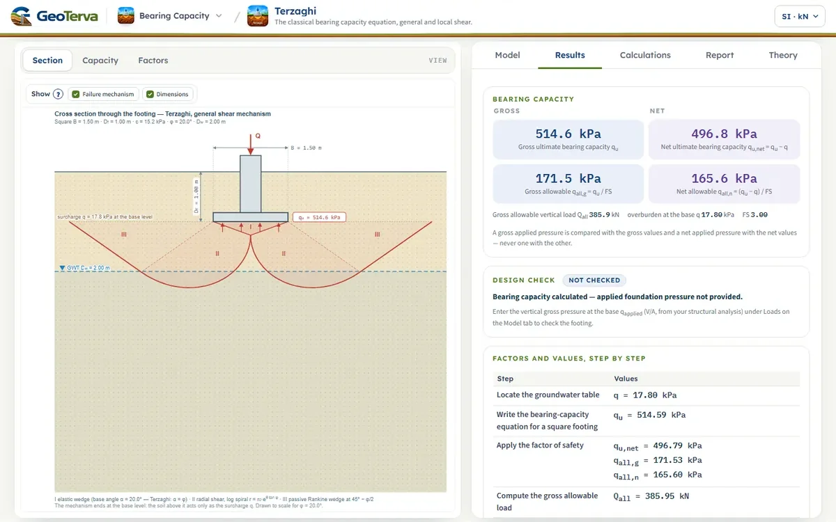
- 13Worked examples
- 14References
Terzaghi’s bearing-capacity theory derived step by step — the failure mechanism, the passive force on the wedge, the three bearing-capacity factors and the equation this module evaluates — followed by square and circular footings, local shear, the water table, the allowable pressure and worked examples. The figures are drawn to scale from the mechanism itself.
 PDF
Lecture slides
Ready-made slides for lectures and self-study
The mechanism, the derivation, the equations and the figures of this page, in teaching order. Every slide links back to its chapter.
1Scope and assumptionsWhat the equation is for, and what it takes for granted.
Terzaghi (1943) found the ultimate bearing capacity qu — the average pressure under a footing at which the soil below it fails in shear — from an assumed failure mechanism and the equilibrium of its parts. This page follows his derivation step by step, in the order of the source, and arrives at the equation this module evaluates. The derivation rests on these assumptions:
- The footing is a long strip (plane strain), rigid, with a rough base: the soil directly under it cannot slide along the base and moves down with the footing as one body.
- The soil below the base is homogeneous and extends to a great depth.
- The load is vertical and central.
- The footing is shallow, Df ≤ B. The soil above the base level takes no part in the mechanism: it only presses on the base level as a surcharge q = γDf, and its shear strength is ignored — a simplification on the safe side.
- The soil fails in general shear (Section 2). Local shear is treated afterwards with reduced strength parameters (Section 10).
The shear strength on a slip surface follows Mohr–Coulomb:
2General and local shear failureTwo ways a footing fails, and the zones under it.
Load a strip footing on dense sand or stiff clay and raise the pressure step by step. Settlement grows slowly at first; then, at a definite pressure, it runs away without any further increase in load: a continuous slip surface has formed from the edge of the footing to the ground surface, and the soil beside the footing heaves. This is general shear failure, and that pressure is the ultimate bearing capacity qu. On loose sand or soft clay the curve has no peak: beyond a pressure q′u it bends onto a steeper, still rising line, the slip surfaces stay inside the soil and the heave is slight — local shear failure.
Under the footing, general shear has three zones: a wedge (I) that moves down with the footing, radial shear zones (II) that the wedge pushes aside, and passive zones (III) that are pushed up and out to the surface. In local shear the same wedge forms, but the shear zones die out in the soil before they reach the surface.
3The failure mechanismTerzaghi’s three zones and the logarithmic spiral.
Terzaghi assumed the failure surface of Figure 4. On each side of the footing it divides the soil into three zones:
- Zone I — the wedge abc under the footing. The rough base holds it, so it moves down with the footing as a rigid body — an “elastic” zone, in which the soil has not failed. Its sides ac and bc are inclined at α = φ to the horizontal.
- Zone II — the radial shear zone bcf, Prandtl’s zone. Every radius from b is a slip line, and the boundary cf is an arc of a logarithmic spiral with its pole at b.
- Zone III — the Rankine passive zone bfg. The soil is in the passive state; its boundaries bf and fg are straight slip lines at 45° − φ/2 to the horizontal. In the real soil fg continues to the ground surface; at the base level only the surcharge q of the soil above is felt.
The spiral cf is
Its useful property: at every point the radius from the pole makes the angle φ with the normal to the curve. On a slip surface at failure, the resultant of the normal stress and the full friction on an element is inclined at φ to the normal — so it lies along the radius and passes through the pole. Friction on the spiral therefore has no moment about the pole, which is why the equilibrium of the following sections is written as moments about it. The angle the spiral sweeps between bc and bf follows from the two straight lines at b:
4The passive force on the wedgeWhy it is vertical, and how it is split into three parts.
At failure the footing pushes the wedge abc down, and the soil of zones II and III resists on each of its faces with a passive force Pp (per unit length of footing). Soil slides past soil along these faces, so the full friction angle acts: Pp is inclined at φ to the normal of the face. The face bc is itself inclined at φ to the horizontal, so its normal is inclined at φ to the vertical — and a force at φ from that normal, on the side of the resisting soil, is exactly vertical. The two passive forces push straight up on the wedge.
Pp depends at once on the surcharge q, the cohesion c and the unit weight γ, and there is no single closed-form solution with all three. Terzaghi split it into three parts, each found as if the other two were zero, and added them (superposition):
- Ppq — the surcharge alone (φ ≠ 0, γ = 0, q ≠ 0, c = 0), Section 5;
- Ppc — the cohesion alone (φ ≠ 0, γ = 0, q = 0, c ≠ 0), Section 6;
- Ppγ — the weight of the soil alone (φ ≠ 0, γ ≠ 0, q = 0, c = 0), Section 7.
The surcharge and the cohesion give a pressure that is the same all along the face, so Ppq and Ppc act at mid-height, h/2; the weight gives a pressure that grows linearly with depth, so Ppγ acts at h/3 above c (Figure 5). The height of the face is
Each part is found in two steps. First, the equilibrium of the soil body bcfj — zone II together with the part of zone III left of the vertical jf through f — gives the passive force on bc. Then the equilibrium of the wedge abc turns that force into a pressure on the footing. Superposition is not exact, because the three parts do not use the same slip surface (Section 8); the error is on the safe side.
5The surcharge term — NqMoments about b for the body bcfj, then the wedge.
With the surcharge alone, the pole of the spiral is at b. Four forces act on the body bcfj (Figure 6 a): the reaction of the wedge, Ppq, on bc; the surcharge q on bj; the Rankine passive force Pp(1) of the soil beyond jf; and the resultant F of the stresses on the spiral cf. The vertical jf has the height Hd; along it the soil is in the Rankine passive state under the surcharge q alone, so the pressure is uniform:
F passes through b (Section 3) and drops out of the moments about b. Ppq acts at the middle of bc, a horizontal distance B/4 from b; the surcharge on bj has its resultant at bj/2; Pp(1) acts at Hd/2 below the base level. Moments about b:
The lengths follow from the spiral — its first radius is bc, its last bf:
Substituting Eq. (6) and Eq. (9) into Eq. (7):
Since tan(45° + φ/2) = cot(45° − φ/2), the second term equals the first, and
With r1 from Eq. (8), and cos φ = 2 sin(45° − φ/2) cos(45° − φ/2), which turns cos²(45° − φ/2)/cos²φ into 1/[4 cos²(45° + φ/2)]:
Now the wedge (Figure 6 b). The footing pressure qq acts on ab = B, and the two vertical forces Ppq hold it up (the weight of the wedge belongs to the γ part):
and with Eq. (12):
For φ = 0 it gives Nq = 1 — without friction the surcharge is carried through unchanged; for φ = 30°, Nq = 22.46.
6The cohesion term — NcThe same body with cohesion; two identities lead to cot φ (Nq − 1).
With the cohesion alone the pole is again at b. The forces on bcfj (Figure 7 a) are: Ppc from the wedge; the cohesive force along bc, C = c·bc = c·r0, which lies along a radius and has no moment about b; the Rankine passive force of the purely cohesive passive state on jf, uniform over the height,
and the cohesion c acting along the spiral. An element ds of the spiral carries the force c·ds along its tangent. The tangent passes at the distance r cos φ from the pole, and ds = r sec φ dθ, so the moment of the element about b is c r² dθ, and the whole arc gives
Moments about b:
With Hd from Eq. (9) and the identity sin²(45° − φ/2)·tan(45° + φ/2) = ½ cos φ, the first term becomes ½ c r1² cos φ; r0 and r1 from Eq. (8) then give
On the wedge (Figure 7 b) the cohesive forces C on the two faces act upward along the faces, each with the vertical component C sin φ:
Substituting Eq. (19) and collecting the terms with and without the exponential:
Two identities simplify the brackets:
so that
As φ → 0 the expression tends to 3π/2 + 1 = 5.71; Terzaghi’s value for φ = 0 is 5.7 (Table 1). For φ = 30°, Nc = 37.16.
7The self-weight term — NγA trial pole, a minimum, and a factor with no closed form.
With the weight of the soil the spiral with its pole at b is no longer the critical one. The pole O is placed on the line fb, extended beyond b, and moved in trials; each position gives another spiral through c and another body bcfj (Figure 8 a). The forces on the body are Ppγ from the wedge, the weight W of the body, the resultant F on the spiral — now through O — and the Rankine passive force on jf, whose pressure grows linearly with depth:
It acts at Hd/3 above f. Moments about O, with the lever arms of Figure 8 a:
The trial is repeated for several positions of O, and the smallest Ppγ is the one the soil develops. The wedge (Figure 8 b) now also carries its own weight,
The minimum Ppγ is written as the passive force on a wall of height h, with a coefficient Kpγ that depends on φ only:
and substituting it into Eq. (29):
Kpγ comes out of the trial minimisation, so Nγ has no closed form; it is computed numerically for each φ. This module uses the values of Kumbhojkar (1993), the series tabulated in Table 1; for φ = 30°, Nγ = 19.13.
8The bearing-capacity equationThe three parts added; the factor table; what superposition costs.
Adding the three parts, the ultimate bearing capacity of a strip footing in soil with cohesion, friction and weight is
with Nq, Nc and Nγ from Eq. (15), Eq. (25) and Eq. (32). They depend on φ alone; Table 1 lists them as the module reads them.
| φ (°) | Nc | Nq | Nγ |
|---|---|---|---|
| 0 | 5.70 | 1.00 | 0.00 |
| 1 | 6.00 | 1.10 | 0.01 |
| 2 | 6.30 | 1.22 | 0.04 |
| 3 | 6.62 | 1.35 | 0.06 |
| 4 | 6.97 | 1.49 | 0.10 |
| 5 | 7.34 | 1.64 | 0.14 |
| 6 | 7.73 | 1.81 | 0.20 |
| 7 | 8.15 | 2.00 | 0.27 |
| 8 | 8.60 | 2.21 | 0.35 |
| 9 | 9.09 | 2.44 | 0.44 |
| 10 | 9.60 | 2.69 | 0.56 |
| 11 | 10.16 | 2.98 | 0.69 |
| 12 | 10.76 | 3.29 | 0.85 |
| 13 | 11.41 | 3.63 | 1.04 |
| 14 | 12.11 | 4.02 | 1.26 |
| 15 | 12.86 | 4.45 | 1.52 |
| 16 | 13.68 | 4.92 | 1.82 |
| 17 | 14.56 | 5.45 | 2.18 |
| 18 | 15.52 | 6.04 | 2.59 |
| 19 | 16.56 | 6.70 | 3.07 |
| 20 | 17.69 | 7.44 | 3.64 |
| 21 | 18.92 | 8.26 | 4.31 |
| 22 | 20.27 | 9.19 | 5.09 |
| 23 | 21.75 | 10.23 | 6.00 |
| 24 | 23.36 | 11.40 | 7.08 |
| 25 | 25.13 | 12.72 | 8.34 |
| φ (°) | Nc | Nq | Nγ |
|---|---|---|---|
| 26 | 27.09 | 14.21 | 9.84 |
| 27 | 29.24 | 15.90 | 11.60 |
| 28 | 31.61 | 17.81 | 13.70 |
| 29 | 34.24 | 19.98 | 16.18 |
| 30 | 37.16 | 22.46 | 19.13 |
| 31 | 40.41 | 25.28 | 22.65 |
| 32 | 44.04 | 28.52 | 26.87 |
| 33 | 48.09 | 32.23 | 31.94 |
| 34 | 52.64 | 36.50 | 38.04 |
| 35 | 57.75 | 41.44 | 45.41 |
| 36 | 63.53 | 47.16 | 54.36 |
| 37 | 70.07 | 53.80 | 65.27 |
| 38 | 77.50 | 61.55 | 78.61 |
| 39 | 85.97 | 70.61 | 95.03 |
| 40 | 95.66 | 81.27 | 116.31 |
| 41 | 106.81 | 93.85 | 140.51 |
| 42 | 119.67 | 108.75 | 171.99 |
| 43 | 134.58 | 126.50 | 211.56 |
| 44 | 151.95 | 147.74 | 261.60 |
| 45 | 172.29 | 173.29 | 325.34 |
| 46 | 196.22 | 204.19 | 407.11 |
| 47 | 224.55 | 241.80 | 512.84 |
| 48 | 258.29 | 287.85 | 650.67 |
| 49 | 298.72 | 344.64 | 831.99 |
| 50 | 347.51 | 415.15 | 1072.80 |
Two remarks on the derivation:
- Nq and Nc use a spiral with its pole at the edge of the footing, Nγ one with its pole at O: the three parts come from two different failure surfaces. Adding separately minimised parts cannot give more than the minimum of the combined problem, so the error of superposition is on the safe side.
- Tests since Terzaghi’s work confirm the shape of the mechanism, but show the sides of the wedge at about 45° + φ/2 to the horizontal rather than at φ (Figure 9). Terzaghi’s factors — and this module — keep α = φ. The wedge at 45° + φ/2 underlies the Prandtl–Reissner factors of the general bearing-capacity equation (the Meyerhof, Hansen and Vesic tools), which is why their Nc and Nq differ from Table 1.
9Square and circular footingsTerzaghi’s coefficients for footings that are not strips.
Under a square or circular footing the soil is not in plane strain, and the derivation does not apply directly. Terzaghi proposed semi-empirical coefficients on the cohesion and weight terms (Table 2):
| Footing | on cNc | on γBNγ | B is |
|---|---|---|---|
| Strip | 1.0 | 0.5 | the width |
| Square | 1.3 | 0.4 | the side |
| Circular | 1.3 | 0.3 | the diameter |
For a saturated clay loaded undrained (φ = 0, c = cu) the factors are Nc = 5.7, Nq = 1 and Nγ = 0:
The Shape choice of the module selects the coefficients. Terzaghi gave none for rectangular footings; the general bearing-capacity equation (Meyerhof, Hansen, Vesic) covers them with shape factors.
10Local shear failureThe same equations with reduced c and φ.
When the soil fails in local shear (Section 2) the mechanism does not fully develop, and only part of the strength is mobilised. Terzaghi kept the same equations and reduced the strength parameters:
The modified factors N′c, N′q and N′γ are the functions of Sections 5–7 evaluated at φ′ (Table 3), and
With c′ = ⅔c the cohesion term of the square and circular footings is 0.867 cN′c.
| φ (°) | φ′ (°) | N′c | N′q | N′γ |
|---|---|---|---|---|
| 0 | 0.00 | 5.70 | 1.00 | 0.00 |
| 1 | 0.67 | 5.90 | 1.07 | 0.01 |
| 2 | 1.33 | 6.10 | 1.14 | 0.02 |
| 3 | 2.00 | 6.30 | 1.22 | 0.04 |
| 4 | 2.67 | 6.51 | 1.31 | 0.05 |
| 5 | 3.34 | 6.74 | 1.40 | 0.07 |
| 6 | 4.01 | 6.97 | 1.49 | 0.10 |
| 7 | 4.68 | 7.22 | 1.59 | 0.13 |
| 8 | 5.35 | 7.48 | 1.70 | 0.16 |
| 9 | 6.03 | 7.74 | 1.82 | 0.20 |
| 10 | 6.70 | 8.03 | 1.94 | 0.25 |
| 11 | 7.38 | 8.32 | 2.08 | 0.30 |
| 12 | 8.07 | 8.63 | 2.23 | 0.36 |
| 13 | 8.75 | 8.97 | 2.38 | 0.42 |
| 14 | 9.44 | 9.31 | 2.55 | 0.49 |
| 15 | 10.13 | 9.67 | 2.73 | 0.58 |
| 16 | 10.82 | 10.06 | 2.93 | 0.67 |
| 17 | 11.52 | 10.47 | 3.14 | 0.77 |
| 18 | 12.22 | 10.90 | 3.37 | 0.89 |
| 19 | 12.93 | 11.36 | 3.61 | 1.03 |
| 20 | 13.64 | 11.86 | 3.88 | 1.18 |
| 21 | 14.35 | 12.38 | 4.17 | 1.35 |
| 22 | 15.07 | 12.92 | 4.49 | 1.54 |
| 23 | 15.80 | 13.52 | 4.83 | 1.76 |
| 24 | 16.53 | 14.15 | 5.20 | 2.01 |
| 25 | 17.27 | 14.82 | 5.61 | 2.29 |
| φ (°) | φ′ (°) | N′c | N′q | N′γ |
|---|---|---|---|---|
| 26 | 18.01 | 15.53 | 6.05 | 2.60 |
| 27 | 18.76 | 16.31 | 6.54 | 2.96 |
| 28 | 19.52 | 17.15 | 7.08 | 3.37 |
| 29 | 20.28 | 18.04 | 7.67 | 3.83 |
| 30 | 21.05 | 18.99 | 8.31 | 4.35 |
| 31 | 21.83 | 20.04 | 9.03 | 4.96 |
| 32 | 22.62 | 21.18 | 9.83 | 5.65 |
| 33 | 23.41 | 22.41 | 10.71 | 6.44 |
| 34 | 24.21 | 23.74 | 11.68 | 7.35 |
| 35 | 25.02 | 25.18 | 12.75 | 8.38 |
| 36 | 25.84 | 26.78 | 13.98 | 9.61 |
| 37 | 26.67 | 28.54 | 15.35 | 11.03 |
| 38 | 27.51 | 30.46 | 16.88 | 12.68 |
| 39 | 28.36 | 32.56 | 18.60 | 14.60 |
| 40 | 29.22 | 34.89 | 20.53 | 16.84 |
| 41 | 30.09 | 37.46 | 22.72 | 19.46 |
| 42 | 30.98 | 40.33 | 25.21 | 22.56 |
| 43 | 31.87 | 43.56 | 28.09 | 26.31 |
| 44 | 32.77 | 47.17 | 31.39 | 30.79 |
| 45 | 33.69 | 51.23 | 35.18 | 36.15 |
| 46 | 34.62 | 55.81 | 39.56 | 42.60 |
| 47 | 35.56 | 61.00 | 44.65 | 50.43 |
| 48 | 36.52 | 66.91 | 50.59 | 60.00 |
| 49 | 37.49 | 73.67 | 57.56 | 71.74 |
| 50 | 38.47 | 81.46 | 65.78 | 86.28 |
For sands, Vesic (1973) proposed a reduction that depends on the relative density Dr instead of the fixed ⅔:
11The water tableWhat the water changes: the surcharge and the weight term.
The derivation assumes the water table far below the footing. A water table closer to it changes two things — the surcharge q and the unit weight in the ½γBNγ term — and never the factors. Below the water table the effective (submerged) unit weight acts:
The module distinguishes three cases (Figure 10):
Case I — above the base, Dw < Df
Case II — at the base, Dw = Df
Case III — below the base, Dw > Df
Deeper than one footing width below the base (D > B) the water lies below the failure zone and the equation is used as if it were absent.
12Allowable pressure and the checkGross and net pressures, and the applied pressure at the base.
qu is the pressure at failure. The module divides it by the factor of safety FS and keeps the gross and the net pressures apart. The gross pressures are the total pressure at the base of the footing; the net pressures are what the footing adds to the overburden q that acted at the base level before the excavation:
The applied pressure qapplied is the vertical gross pressure at the base under service loads: V, Wf and Ws over the base area A (B² for a square, πB²/4 for a circle, B per unit length for a strip). The footing passes when
With q ≥ 0 and FS ≥ 1 the gross check governs: when it passes, the net check passes too. Without qapplied the module reports the capacities only and does not declare the footing adequate. A factor of safety of about 3 is usual; it covers the uncertainty of the strength parameters more than that of the theory.
13Worked examplesGeneral shear, local shear, and the water table — computed live.
A square footing 1.5 m × 1.5 m at Df = 1 m, in soil with φ = 20°, c = 15.2 kPa and γ = 17.8 kN/m³. The numbers below are computed with the module’s own table and interpolation, and shown rounded.
First case — general shear, no water table
For φ = 20°, Table 1 gives Nc = 17.69, Nq = 7.44, Nγ = 3.64, and q = γDf = 17.80 kPa. With Eq. (35):
Second case — the same footing in local shear
φ′ = tan−1(⅔ tan 20°) = 13.64°, c′ = ⅔ × 15.2 = 10.13 kPa; Table 3 gives N′c = 11.86, N′q = 3.88, N′γ = 1.18:
Third case — with a water table: the module’s opening model
The water table at Dw = 2 m, γsat = 19 kN/m³: D = Dw − Df = 1.00 m ≤ B, Case III. The surcharge is unchanged; the weight term takes
These are the numbers the module opens with; its Results and Calculations tabs give the same values.
14ReferencesSources of the theory and of the factors.
- Terzaghi, K. (1943). Theoretical Soil Mechanics. Wiley, New York.
- Das, B.M. (2017). Shallow Foundations: Bearing Capacity and Settlement, 3rd ed. CRC Press, Boca Raton — Sections 2.2–2.3; this page follows the order of its derivation.
- Das, B.M. (2018). Principles of Geotechnical Engineering, 9th ed. Cengage Learning — Chapter 16: the groundwater cases, the factor of safety, Table 16.1.
- Kumbhojkar, A.S. (1993). Numerical evaluation of Terzaghi’s Nγ. Journal of Geotechnical Engineering, ASCE, 119(3), 598–607.
- Prandtl, L. (1921). Über die Eindringungsfestigkeit (Härte) plastischer Baustoffe und die Festigkeit von Schneiden. ZAMM, 1(1), 15–20.
- Vesic, A.S. (1973). Analysis of ultimate loads of shallow foundations. Journal of the Soil Mechanics and Foundations Division, ASCE, 99(SM1), 45–73.
The figures of this page are drawn from the mechanism itself; the equation, figure and table numbers are its own.
From theory to your own design
Find the bearing capacity of your own footing in minutes
- The ultimate and the allowable bearing capacity, gross and net, term by term
- General or local shear, with the water table at any depth
- The failure zones drawn to scale under your footing
- A clean calculation report, saved as a PDF. Online: nothing to install, no dongle, on a phone, a tablet or a PC