
On this page · 15 chapters
- 1The general equation
- 2Meyerhof’s slip-line field
- 3Stresses on the equivalent free surface
- 4The radial zone and the wedge — Nc and Nq
- 5The angle θ and the surface footing
- 6The self-weight term — Nγ
- 7The bearing-capacity factors
- 8Shape factors
- 9Depth factors
- 10Inclination factors
- 11The complete equation
- 12The water table
- 13Allowable pressure and the check
- 14Worked example
- 15References
Meyerhof’s bearing-capacity theory derived step by step — the slip-line field with the equivalent free surface, the stresses on it, the equilibrium that gives Nc and Nq, the surface footing and the trial procedure for Nγ — followed by the shape, depth and inclination factors of the general equation this module evaluates, the water table, the allowable pressure and a worked example. The figures are drawn to scale from the mechanism itself.
 PDF
Lecture slides
Ready-made slides for lectures and self-study
The mechanism, the derivation, the equations and the figures of this page, in teaching order. Every slide links back to its chapter.
1The general equationWhat the module evaluates, and where the factors come from.
This module evaluates the general bearing-capacity equation: the three terms of Terzaghi’s equation, each with its own factors for the shape of the footing, its depth and the inclination of the load,
Its bearing-capacity factors Nc and Nq come from Meyerhof’s theory (1951), which this page derives step by step in the order of the source: the slip-line field under a rough continuous footing (Section 2), the stresses on the equivalent free surface (Section 3), the equilibrium of the radial zone and of the wedge, which gives Nc and Nq (Sections 4–5), and the trial procedure for Nγ (Section 6). The correction factors follow in Sections 8–10.
- The footing is rough; below it the soil is homogeneous and extends to a great depth; its strength is s = c + σ′ tan φ.
- Unlike Terzaghi’s, Meyerhof’s theory is not limited to shallow footings: the soil above the base level takes part in the mechanism through the equivalent free surface. In the equation this appears as the depth factors, so the module places no limit on Df/B.
- The load is central; an inclined load is handled by the inclination factors (Section 10).
2Meyerhof’s slip-line fieldThe wedge at 45° + φ/2, the radial zone and the equivalent free surface.
Meyerhof (1951) took the failure surface of Figure 1. Under the footing is the same elastic wedge abc that tests show — its sides are inclined at 45° + φ/2, not at φ as Terzaghi assumed. Beside it lies the radial shear zone bcd, bounded by an arc of the log spiral r = r0 eθ tan φ with its pole at b. Beyond it Terzaghi had a Rankine passive zone; Meyerhof has a mixed shear zone bde, in which the shear lies between the limits of radial and plane shear, depending on the depth and the roughness of the footing.
The soil above the zone bde is not ignored. Its effect is replaced by the stresses it exerts on the plane be, the equivalent free surface: a normal stress po and a shear stress so. The plane is inclined at β to the horizontal, and bd lies at the angle η below it. The capacity is again built up by superposition — the contribution of c and po (Nc, Nq) and that of the weight γ (Nγ):
3Stresses on the equivalent free surfacePartial mobilisation m, the Mohr circle of the zone bde, and the angle η.
On the equivalent free surface the shear strength is only partly mobilised. Meyerhof wrote the shear stress there as a fraction m of the strength:
In the linear zone bde, on the other hand, the soil is in plastic equilibrium: on the plane bd the full strength is mobilised under the normal stress p1,
The state of stress in bde is one Mohr circle of radius R (Figure 2). The point of bd lies on the envelope, so
and the point of be, 2η further round the circle, has the shear stress
With Eq. (3) and Eq. (4) this fixes the angle η by the mobilisation m:
The centre of the circle lies at p1 + R sin φ = po + R sin(2η + φ), which gives the normal stress on bd:
The two limits of mobilisation give the two limits of η:
4The radial zone and the wedge — Nc and NqMoments about b, then the vertical balance of the wedge.
On the face bc the soil of zone bcd is also at failure, so its normal and shear stresses are related by
Moments about the pole b (Figure 3 a): the shear stresses on bd and bc act along radii and F passes through b, so only the normal stresses and the cohesion on the spiral remain. p1 acts on r1 = bd and p′p on r0 = bc, each with its resultant at mid-length:
Solving for p′p, and then s′p from Eq. (11):
Now the wedge abc (Figure 3 b). Each face has the length (B/2)/cos(45° + φ/2); the normal stress p′p contributes its component cos(45° + φ/2), the shear stress s′p its component sin(45° + φ/2) to the vertical balance with the footing pressure q′:
Substituting Eq. (8), Eq. (14) and Eq. (15) into Eq. (17) and simplifying separates the terms in c and in po:
5The angle θ and the surface footingHow β and m enter, and Reissner’s and Prandtl’s closed forms.
The factors depend on φ, on the mobilisation m through η, and on the inclination β of the equivalent free surface through the angle θ the spiral sweeps. From the geometry of Figure 1:
A deeper footing has a steeper equivalent free surface and a larger β, and Figure 4 shows how fast the factors grow with it. For a surface footing — the condition of Terzaghi’s derivation — β = 0 and m = 0, so θ = π/2 and sin(2η + φ) = 1:
These are Reissner’s (1924) Nq and Prandtl’s (1921) Nc, and they are the factors this module uses. With po = γDf = q the c and q terms of the equation become cNc + qNq; the soil above the base, which Meyerhof represented by β and m, is credited instead by the depth factors (Section 9). As φ → 0, Nc tends to π + 2 = 5.14.
6The self-weight term — NγMeyerhof’s trial procedure, his 1963 approximation, and the Nγ used here.
As in Terzaghi’s theory, Nγ has no closed form; it is found by trial (Figure 5):
- Choose φ and the inclination β of the equivalent free surface, and a mobilisation m (0 or 1).
- Find θ from Eq. (21), and draw the lines bd and be.
- Choose a trial centre O and draw the arc of a log spiral r = r0eθ tan φ from c to the line bd; call its end d.
- Draw df at 90° − φ to bd — both are slip lines of the linear zone, so the trial surface generally has a corner at d.
- For the body bcdf find its weight W and the Rankine passive force Pp(R) on df.
- Take moments about O and solve for the passive force on bc,
and repeat for other centres O until the minimum Ppγ is found. The wedge abc, with its own weight Ww and the force Ppγ on each face (inclined at φ to the normal, so its vertical component is Ppγ sin(45° + φ/2)), then gives
Adding the two parts, qu = q′ + q″ = cNc + poNq + ½γBNγ — the form of Eq. (2). For a surface footing (β = 0, m = 0) Meyerhof (1963) approximated his Nγ by
The Nγ of this module
This module uses the Nγ of the general bearing-capacity equation as the second source presents it — Vesic’s (1973) closed form:
The two agree on Nc and Nq but not on Nγ: at φ = 30°, Vesic’s is 22.40 and Meyerhof’s 15.67. Nγ is the factor on which the methods differ most, because it depends on the shape assumed for the wedge. Table 1 lists both; with Meyerhof’s Nγ the self-weight term, and therefore qu of a frictional soil, would be lower.
7The bearing-capacity factorsNc, Nq, Nγ from φ = 0 to 50°.
The factors depend on φ alone:
| φ (°) | Nc | Nq | Nγ | Nγ M. |
|---|---|---|---|---|
| 0 | 5.14 | 1.00 | 0.00 | 0.00 |
| 1 | 5.38 | 1.09 | 0.07 | 0.00 |
| 2 | 5.63 | 1.20 | 0.15 | 0.01 |
| 3 | 5.90 | 1.31 | 0.24 | 0.02 |
| 4 | 6.19 | 1.43 | 0.34 | 0.04 |
| 5 | 6.49 | 1.57 | 0.45 | 0.07 |
| 6 | 6.81 | 1.72 | 0.57 | 0.11 |
| 7 | 7.16 | 1.88 | 0.71 | 0.15 |
| 8 | 7.53 | 2.06 | 0.86 | 0.21 |
| 9 | 7.92 | 2.25 | 1.03 | 0.28 |
| 10 | 8.34 | 2.47 | 1.22 | 0.37 |
| 11 | 8.80 | 2.71 | 1.44 | 0.47 |
| 12 | 9.28 | 2.97 | 1.69 | 0.60 |
| 13 | 9.81 | 3.26 | 1.97 | 0.74 |
| 14 | 10.37 | 3.59 | 2.29 | 0.92 |
| 15 | 10.98 | 3.94 | 2.65 | 1.13 |
| 16 | 11.63 | 4.34 | 3.06 | 1.37 |
| 17 | 12.34 | 4.77 | 3.53 | 1.66 |
| 18 | 13.10 | 5.26 | 4.07 | 2.00 |
| 19 | 13.93 | 5.80 | 4.68 | 2.40 |
| 20 | 14.83 | 6.40 | 5.39 | 2.87 |
| 21 | 15.81 | 7.07 | 6.20 | 3.42 |
| 22 | 16.88 | 7.82 | 7.13 | 4.07 |
| 23 | 18.05 | 8.66 | 8.20 | 4.82 |
| 24 | 19.32 | 9.60 | 9.44 | 5.72 |
| 25 | 20.72 | 10.66 | 10.88 | 6.77 |
| φ (°) | Nc | Nq | Nγ | Nγ M. |
|---|---|---|---|---|
| 26 | 22.25 | 11.85 | 12.54 | 8.00 |
| 27 | 23.94 | 13.20 | 14.47 | 9.46 |
| 28 | 25.80 | 14.72 | 16.72 | 11.19 |
| 29 | 27.86 | 16.44 | 19.34 | 13.24 |
| 30 | 30.14 | 18.40 | 22.40 | 15.67 |
| 31 | 32.67 | 20.63 | 25.99 | 18.56 |
| 32 | 35.49 | 23.18 | 30.21 | 22.02 |
| 33 | 38.64 | 26.09 | 35.19 | 26.17 |
| 34 | 42.16 | 29.44 | 41.06 | 31.15 |
| 35 | 46.12 | 33.30 | 48.03 | 37.15 |
| 36 | 50.59 | 37.75 | 56.31 | 44.43 |
| 37 | 55.63 | 42.92 | 66.19 | 53.27 |
| 38 | 61.35 | 48.93 | 78.02 | 64.07 |
| 39 | 67.87 | 55.96 | 92.25 | 77.33 |
| 40 | 75.31 | 64.20 | 109.41 | 93.69 |
| 41 | 83.86 | 73.90 | 130.21 | 113.99 |
| 42 | 93.71 | 85.37 | 155.54 | 139.32 |
| 43 | 105.11 | 99.01 | 186.53 | 171.14 |
| 44 | 118.37 | 115.31 | 224.63 | 211.41 |
| 45 | 133.87 | 134.87 | 271.75 | 262.74 |
| 46 | 152.10 | 158.50 | 330.34 | 328.73 |
| 47 | 173.64 | 187.21 | 403.65 | 414.33 |
| 48 | 199.26 | 222.30 | 496.00 | 526.45 |
| 49 | 229.92 | 265.50 | 613.14 | 674.92 |
| 50 | 266.88 | 319.06 | 762.86 | 873.86 |
8Shape factorsDe Beer’s correction for a footing that is not a strip.
The derivation is for a continuous footing (plane strain). A rectangular footing fails in three dimensions, and the soil can move round the ends of the wedge as well as sideways. De Beer’s (1970) shape factors correct each term with the ratio of the short side to the long side, B/L:
For a strip all three are 1 and the equation returns to the plane-strain form.
9Depth factorsHansen’s credit for the soil above the base.
Terzaghi’s equation counts the soil above the base as dead weight only. In Meyerhof’s theory it also resists through the equivalent free surface; in the general equation this is credited by Hansen’s (1970) depth factors, which grow with Df/B:
Beyond Df/B = 1 the arctangent keeps the factors growing, but ever more slowly — which is why this equation, unlike Terzaghi’s, needs no limit on the depth.
10Inclination factorsMeyerhof’s reduction for an inclined load.
A load inclined at β to the vertical mobilises less vertical resistance than a vertical one: part of it pushes the footing sideways. Meyerhof’s (1963) inclination factors reduce each term:
At β = 0 all three are 1. Fγi reaches zero at β = φ and stays there — the module does not let (1 − β/φ)² grow again — and β is accepted up to 89°, below the point where (1 − β/90°)² would start to grow.
11The complete equationAll factors together; the undrained case.
With the factors of Sections 5–10 the general equation Eq. (1) is complete. For a strip footing under a vertical load at the base level all correction factors are 1, and the equation has the form of Terzaghi’s — with Reissner’s Nq, Prandtl’s Nc and Vesic’s Nγ in place of Terzaghi’s factors.
For undrained loading (φ = 0, c = cu) Nc = 5.14, Nq = 1 and Nγ = 0:
The water table enters the equation exactly as in Terzaghi’s (Section 12): through q and the unit weight of the third term, never through the factors.
12The water tableThe surcharge and the weight term; the factors are unchanged.
Below the water table the effective unit weight γ′ = γsat − γw acts (γw = 9.81 kN/m³). The module distinguishes three cases, Dw being the depth of the water table below the ground surface:
Case I — above the base, Dw < Df
Case II — at the base, Dw = Df
Case III — below the base, Dw > Df
Deeper than one footing width below the base the water has no effect.
13Allowable pressure and the checkGross and net pressures, and the allowable resultant at β.
qu is the vertical pressure at failure. The module keeps the gross and the net pressures apart:
The applied pressure qapplied is the vertical gross pressure at the base under service loads, V/A — with an inclined load its vertical component, not the resultant over the area. The footing passes when
The allowable vertical load is Qall = qall,g·A; the allowable resultant load at the inclination β is Qall/cos β. Without qapplied the module reports the capacities only.
14Worked exampleThe module’s opening model, computed live.
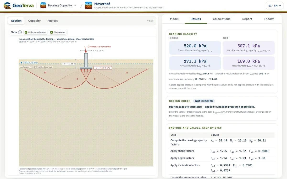
A square footing 1.2 m × 1.2 m at Df = 1 m in sand, φ = 32°, c = 0, γ = 16 kN/m³ above and γsat = 19.5 kN/m³ below a water table at Dw = 0.5 m; the load is inclined at β = 10°. This is the module’s opening model, computed here with its own functions.
Water above the base (Case I): q = 0.5(16) + (19.5 − 9.81)(0.5) = 12.845 kPa, and γ′ = 9.69 kN/m³ in the third term. B/L = 1; Df/B = 0.833 ≤ 1; β = 10° < φ:
With c = 5 kPa the cohesion term adds c Nc Fcs Fcd Fci = 287.51 kPa (Fcd = 1.241 from Fqd), and qu = 807.50 kPa. Both numbers are in the module’s check set.
15ReferencesSources of the theory and of the factors.
- Meyerhof, G.G. (1951). The ultimate bearing capacity of foundations. Géotechnique, 2(4), 301–332.
- Meyerhof, G.G. (1963). Some recent research on the bearing capacity of foundations. Canadian Geotechnical Journal, 1(1), 16–26.
- Das, B.M. (2017). Shallow Foundations: Bearing Capacity and Settlement, 3rd ed. CRC Press — Sections 2.4–2.5; this page follows the order of its derivation; “the source” in the text of this page.
- Das, B.M. (2016). Principles of Foundation Engineering, 8th ed. Cengage — the general bearing-capacity equation and its factors; “the second source” in the text of this page.
- Reissner, H. (1924). Zum Erddruckproblem. Proc. 1st Int. Congress of Applied Mechanics, Delft, 295–311.
- Prandtl, L. (1921). Über die Eindringungsfestigkeit (Härte) plastischer Baustoffe und die Festigkeit von Schneiden. ZAMM, 1(1), 15–20.
- Vesic, A.S. (1973). Analysis of ultimate loads of shallow foundations. JSMFD, ASCE, 99(SM1), 45–73.
- De Beer, E.E. (1970). Experimental determination of the shape factors and the bearing capacity factors of sand. Géotechnique, 20(4), 387–411.
- Hansen, J.B. (1970). A revised and extended formula for bearing capacity. Danish Geotechnical Institute Bulletin 28.
The figures are drawn from the mechanism itself; the chart of Nq is computed from the equations of this page.
From theory to your own design
Find the Meyerhof capacity of your own footing in minutes
- Every factor with its formula, and the capacity gross and net
- A strip, square, rectangular or circular footing under a vertical or an inclined load
- The mechanism drawn on the section
- A clean calculation report, saved as a PDF. Online: nothing to install, no dongle, on a phone, a tablet or a PC