
On this page · 5 chapters
The vertical stress below a uniformly loaded flexible rectangle: I3 below a corner, any point by corner superposition, and I4 below the centre. The figures are computed from the equations.
 PDF
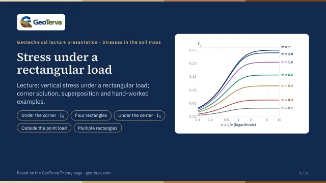
Lecture slides
Ready-made slides for lectures and self-study
The mechanism, the derivation, the equations and the figures of this page, in teaching order. Every slide links back to its chapter.
1Scope and assumptionsA uniformly loaded rectangle.
Most footings and rafts are rectangular. Integrating Boussinesq's point-load solution over a rectangle gives the vertical stress below one of its corners in closed form; every other point follows by adding and subtracting rectangles.
- A flexible rectangle L × B with a uniform pressure q.
- The soil is a homogeneous, isotropic, linearly elastic half-space.
- Δσz is an increase caused by the load only.
2Below a cornerΔσz = qI3.
The elemental area carries dq = q dx dy. With P = q dx dy and r² = x² + y² in Boussinesq's equation,
and over the whole rectangle
where, with m = B/z and n = L/z,
The arctangent must be a positive angle in radians; when m² + n² + 1 < m²n² it comes out negative and π is added. I3 is symmetric in m and n and tends to 1/4 for a very large rectangle — a corner carries a quarter of the load of an infinite area.
| n | m = 0.1 | m = 0.2 | m = 0.5 | m = 1 | m = 2 | m = 3 |
|---|---|---|---|---|---|---|
| 0.1 | 0.0047 | 0.0092 | 0.0198 | 0.0279 | 0.0311 | 0.0315 |
| 0.25 | 0.0113 | 0.0220 | 0.0475 | 0.0674 | 0.0752 | 0.0761 |
| 0.5 | 0.0198 | 0.0387 | 0.0840 | 0.1202 | 0.1350 | 0.1368 |
| 1 | 0.0279 | 0.0547 | 0.1202 | 0.1752 | 0.1999 | 0.2034 |
| 2 | 0.0311 | 0.0610 | 0.1350 | 0.1999 | 0.2325 | 0.2378 |
| 5 | 0.0316 | 0.0620 | 0.1374 | 0.2044 | 0.2395 | 0.2461 |
3Any point, and the centreSuperposition of corner rectangles.
Below any point A′ the loaded area is divided into rectangles with a common corner above A′, and their corner stresses add:
When A′ lies outside the area, some of the rectangles extend beyond it and are subtracted, as in the worked example below. The module does this for every point with signed distances: the four rectangles run from the point to the four corners of the load, and each I3 takes the sign of the product of its two sides.
Below the centre the four rectangles are equal, and the result can be written directly:
with m1 = L/B, n1 = z/b and b = B/2 (L ≥ B). For a square at z = b: I4 = 0.701 = 4 I3(1, 1).
4Worked exampleEvery number computed by the module’s own code.
For the 4 m × 2 m rectangle m = 2/4 = 0.5, n = 4/4 = 1; for the 1 m × 2 m one m = 1/4 = 0.25, n = 2/4 = 0.5:
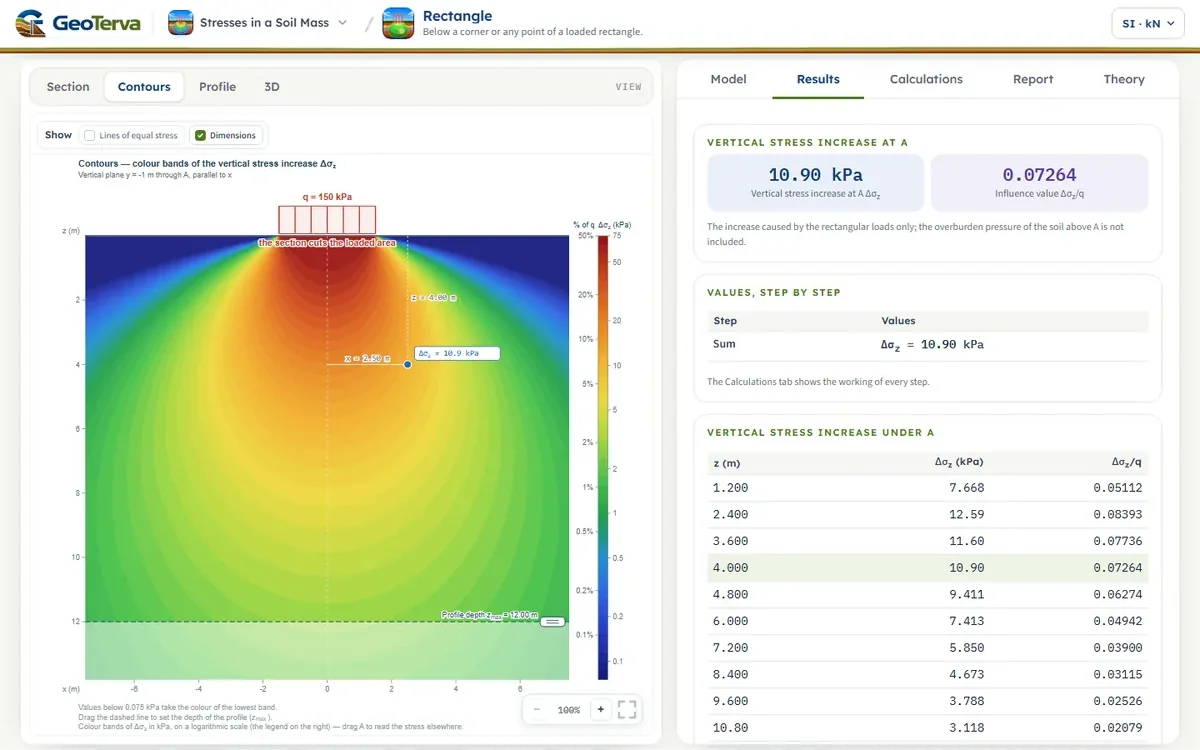
The module opens with this example (the rectangle centred on the origin, A′ at x = 2.5 m, y = −1 m). Further rectangles, each with its own q, sides and centre on the ground, are put in one by one with Add rectangular load (up to eight); two rectangles may meet at a side but not overlap and, the soil being elastic, the stress of each is found by its own four corner rectangles and the stresses add.
5ReferencesSources.
- Das, B.M. (2018). Principles of Geotechnical Engineering, 9th ed. Cengage Learning.
- Boussinesq, J. (1883). Application des Potentiels à l'Étude de l'Équilibre et du Mouvement des Solides Élastiques. Gauthier-Villars, Paris.
From theory to your own design
Find the stress below your own rectangular load in minutes
- The vertical stress increase at any point below or beside one or several rectangles
- The influence value of each corner rectangle
- Contours of equal stress and a depth profile
- A clean calculation report, saved as a PDF. Online: nothing to install, no dongle, on a phone, a tablet or a PC