
On this page · 19 chapters
- 1The model of the wall
- 2Model at a glance
- 3Coordinates, free body, force ledger and sign convention
- 4Geometry decomposition: parts, centroids and lever arms
- 5The soil moving with the wall: the block behind the wall, zones, moist and saturated weight
- 6Effective stress and groundwater
- 7Rankine active and passive earth pressure
- 8Coulomb earth pressure on the vertical plane
- 9At-rest pressure and passive resistance in front of the wall
- 10Surcharge loads
- 11Hydrostatic water on both sides and uplift
- 12Mononobe–Okabe seismic earth pressure
- 13Hydrodynamic water
- 14Inertia of the wall and of the soil moving with it
- 15Sliding, overturning and bearing
- 16Scope of the checks
- 17Worked example: a wall calculated step by step
- 18Variables
- 19References
The wall is treated as a rigid gravity block of stone masonry or plain concrete per unit length — a trapezoidal body on a stepped footing. The retained side consists of one soil layer and may include a sloping backfill, uniform surcharge and groundwater; the soil in front of the wall may add a passive resistance to the sliding check.
 PDF
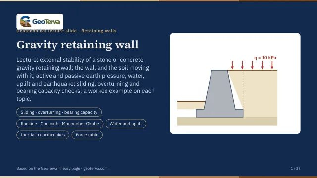
Lecture slides
Ready-made slides for lectures and self-study
The mechanism, the derivation, the equations and the figures of this page, in teaching order. Every slide links back to its chapter.
1The model of the wallWhat is analysed, and how it is drawn.
Analysis concept
Rankine · static
Suitable for a conventional active/passive earth-pressure idealization. Wall friction is not explicitly used in the classical Rankine coefficient.
Coulomb · static
Acts on the vertical plane through the back edge of the footing (soil against soil) with δ = β, so no wall friction is used; for this plane (α = 90°, δ = β) the Coulomb Kₐ equals the Rankine Kₐβ exactly.
Mononobe–Okabe · seismic
The seismic earth pressure is always the Mononobe–Okabe pseudo-static thrust: the Coulomb wedge with the inertia forces kₕ·W and ±kᵥ·W added, solved on the same pressure plane as the static case (the vertical plane at x = B, δ = β).
Uniform surcharge
A uniform surface surcharge produces an additional lateral pressure. It is reported separately from the soil self-weight component; its vertical load over the wall is not counted as stabilising.
Theory manual
The overview above summarises the model. The manual below is written as a self-contained manual: every quantity that appears in the Calculations tab is explained from its physical idea, drawn, derived and then tied to the exact way the solver evaluates it. A complete numerical example (Section 16) is computed by the same engine that runs the tool, so every substitution printed there can be checked by hand.
2Model at a glanceGroundwater, the wall material, the stability checks and the symbols of the overview.
Groundwater & effective stress
Below the groundwater table, effective vertical stress is calculated using the submerged soil unit weight while hydrostatic water pressure is applied independently. If retained-side and front-side water levels differ, the wall experiences a net water-pressure component and the project should also consider the appropriate hydraulic stability/seepage condition.
Wall material
Stone masonry (γm = 22 kN/m³ by default) or plain concrete (24 kN/m³); the unit weight can be changed. The wall acts by its weight: the body and the footing, and the soil standing on the back footing, hold the thrust of the backfill.
Stability checks
Sliding
Resistance is the base friction μb·N plus the front resistance Ptoe; no base adhesion is used.
Overturning
Moments are taken about the toe — the front bottom corner of the footing.
Bearing pressure
The result is checked against no-tension/contact criteria and the allowable bearing pressure.
Internal stresses
The checks of this module are those of a rigid block on its foundation. The compression, tension and joint sliding inside the masonry or concrete are verified with the governing masonry or concrete code, using the actions of the Calculations tab (section 15 of the manual).
Variables
3Coordinates, free body, force ledger and sign conventionFree body, force ledger, M = x·Fz − z·Fx.
Stability is an equilibrium problem, so the first step is to decide what is in equilibrium and how forces and moments are signed. Mixing conventions (for example taking some moments "clockwise positive" and others "overturning positive") is the most common source of error in hand calculations; GeoTerva therefore uses one Cartesian system for everything.
Coordinates
The origin O is at the toe, the front bottom corner of the footing, on the base underside. x points toward the backfill and z upward. The front footing top is at z = Hfl, the back footing top at z = Hfr, the wall top at z = H, and the back edge of the footing at x = B = Wbl + Wdl + Wu + Wdr + Wbr.
Forces and the moment about the toe
A force acting on the free body is written by its components (Fx, Fz) and a point on its line of action (x, z). Its moment about O is the two-dimensional cross product r × F:
Why this sign is "overturning positive". A weight W at x > 0 has Fz = −W, so M = −x·W < 0: it holds the wall back. An earth thrust at height z pushing toward the front has Fx < 0, so M = −z·Fx > 0: it turns the wall over the toe. Uplift (Fz > 0) gives M > 0, front resistance (Fx > 0) gives M < 0. No force category is hard-coded as "resisting": each of the two parts x·Fz and −z·Fx is classified by its own sign. The vertical component of an inclined earth thrust, for example, is correctly counted as resisting.
The free body
The free body is the wall plus the soil that moves with it (the block behind the wall of Section 4, and the fill over the front footing). It is cut out along the base underside and along the external pressure plane. Everything that acts across those cuts, and every body force inside them, is one entry of the force ledger. The three checks read the same ledger, so a force can never be forgotten in one check and counted in another.
| Ledger id | Force | Sliding | Overturning | Bearing |
|---|---|---|---|---|
W_CONCRETE | Wall self-weight, all parts (stone masonry or plain concrete; the id is the same for both) | yes | yes | yes |
W_SOIL_HEEL | Soil moving with the wall — over the back footing and against the back batter (γ above, γsat below the GWT) | yes | yes | yes |
Q_HEEL | Surcharge over the soil behind the wall — a favourable load that may be absent, always excluded | no | no | no |
W_SOIL_TOE | Fill over the front footing — it moves with the wall | yes | yes | yes |
PA_STATIC, PA_Q | Static active thrust of the soil and of the surcharge | yes | yes | yes |
PA_SP | Lateral pressure of the strip and point loads (rigid-wall elastic solutions), all cases at full value | yes | yes | yes |
PAE_TOTAL | Total seismic active thrust (soil + surcharge) | yes | yes | yes |
U_REAR, U_FRONT | Hydrostatic water on the retained and front sides | yes | yes | yes |
UPLIFT | Water pressure on the base underside | yes | yes | yes |
HD_REAR, HD_FRONT | Hydrodynamic water in the seismic cases (retained and front side) | yes | yes | yes |
IH_W_…, IV_W_… | Horizontal and vertical inertia of the wall, the soil behind it and the fill over the front footing | yes | yes | yes |
PP_FRONT | Front soil resistance on the vertical plane at the toe | yes | no | no |
How the checks read the ledger
PP_FRONT onlyA front-side water force has Fx > 0 and therefore reduces ΣHdrive. Section 14 derives the three factors of safety from these sums.
4Geometry decomposition: parts, centroids and lever armsFront block, batters, core, back block; centroids and lever arms.
The self-weight of the wall and its moment about the toe are the backbone of both stability checks — for a gravity wall they are most of the resistance. A hand calculation splits the section into simple shapes whose area and centroid are known, computes Wi = γm·Ai for each and adds the moments Wi·x̄i. GeoTerva does exactly the same (the component table of the Calculations tab) and, as an independent check, also computes the whole outline as one polygon; the two must agree to 10⁻⁹.
The parts
| Part | Shape and area A | x̄ from the toe | z̄ from the base underside |
|---|---|---|---|
| C₁ Front block | rectangle, (Wbl + Wdl)·Hfl | (Wbl + Wdl)/2 | Hfl/2 |
| C₂ Front batter | triangle, ½·Wdl·(H − Hfl) | Wbl + 2Wdl/3 | Hfl + (H − Hfl)/3 |
| C₃ Core | rectangle, Wu·H | Wbl + Wdl + Wu/2 | H/2 |
| C₄ Back batter | triangle, ½·Wdr·(H − Hfr) | Wbl + Wdl + Wu + Wdr/3 | Hfr + (H − Hfr)/3 |
| C₅ Back block | rectangle, (Wdr + Wbr)·Hfr | Wbl + Wdl + Wu + (Wdr + Wbr)/2 | Hfr/2 |
Weights and moments
In the ledger the wall is one entry W_CONCRETE with Fz = −Wm at (x̄m, z̄m), so its moment is M = −Wm·x̄m = −ΣMi. The height z̄m is needed only for the horizontal inertia kh·Wm of Section 13. γm is the unit weight of the wall material: 22 kN/m³ for stone masonry and 24 kN/m³ for plain concrete by default (the value can be changed; a dry-stone wall with open joints is lighter).
5The soil moving with the wall: the block behind the wall, zones, moist and saturated weightThe soil block behind the wall, pressure plane, moist and saturated zones.
Why does the earth pressure not act simply on the back batter of the wall? Because the soil standing on the back footing cannot slide relative to it: when the wall moves, that soil moves with it. In the limiting state the backfill behind it reaches failure along planes that start at the back edge of the footing, not on the batter. The mechanically consistent free body is therefore the wall plus this soil block, loaded by the earth pressure on its outer face — the external pressure plane (often called the virtual back).
The plane runs from the ground surface above the back edge (x = B, z = zground(B)) down to the base underside. On a sloping backfill it therefore includes the rise of the ground over the block. Above the back footing top (z = Hfr) it is the virtual soil–soil plane; over the footing height (z = 0 … Hfr) it is the end face of the back footing, and the same pressure is applied down to the base underside, as in the standard hand calculation (the source, Bowles). Everything between the plane and the back of the wall is weight. A wall with Wdr = Wbr = 0 has a vertical back face at x = B and no soil block; the plane is then the back of the wall itself, still with δ = β — no wall friction is credited.
The seismic case uses the same plane: the Mononobe–Okabe wedge is solved on the vertical plane at x = B with δ = β; its height is h = zground(B) = H + the rise of the slope over the back of the wall.
Zones
For the component table the soil is clipped into named zones, each split at the water table into a moist part (unit weight γ) and a saturated part (γsat):
| Zone id | Region |
|---|---|
S_HEEL | Soil behind the wall: over the back footing and against the back batter, from the back footing top to wall-top level |
S_SLOPE | The wedge of sloping ground above wall-top level |
S_TOE | Fill over the front footing: from the front footing top to the front ground, when Df > Hfl |
Why γsat and not γ′ below the water table? The free body is written in total stress: the soil is weighed with its pore water, and the water pressure on the boundary of the free body (U_REAR on the pressure plane, UPLIFT on the base underside) is applied as separate forces. By Archimedes, total weight minus the resultant of the boundary water pressure equals the effective (buoyant) weight, so the two descriptions are identical — but mixing them (γ′ and uplift) would count buoyancy twice.
Excluded vertical load. The surcharge over the soil behind the wall (Q_HEEL) is a favourable vertical load that may be absent when the lateral load acts: it is listed in the ledger as excluded and enters no check, while it still pushes on the plane. The fill over the front footing (W_SOIL_TOE) is different: it rests on the footing and moves with the wall, so its weight is a vertical load — in N, in the resisting moment and in the bearing resultant — and the front soil still provides the passive resistance of Section 8. Enter Df = 0 when the front soil may be removed.
6Effective stress and groundwaterσ′v, pore pressure, γ′ and the porosity of the backfill.
Soil strength and therefore earth pressure are governed by the effective stress — the part of the total stress carried by the grain skeleton. Water has no shear strength: it pushes equally in every direction and is added to the lateral pressure with a coefficient of one. Every lateral pressure in GeoTerva is therefore built in two separate layers: K·σ′v from the soil and u from the water.
Governing equations
ddry is the depth above the water table and dsub the depth below it, both measured from the top of the pressure plane, the ground surface above the back edge of the footing. A uniform surcharge adds q to σ′v at every depth.
Porosity of the backfill
The seismic pore-water assumption (Section 12) needs the dry (skeleton) unit weight, which is not an input. It follows from the phase relations with the specific gravity of the solids, Gs = 2.65 — an internal constant of the module, not an input. With void ratio e, γsat = (Gs + e)·γw/(1 + e); with porosity n = e/(1 + e) this becomes γsat = [Gs(1 − n) + n]·γw, and solving for n:
For γsat = 20 kN/m³, γw = 9.81 kN/m³ and Gs = 2.65: n = (2.65·9.81 − 20)/(1.65·9.81) = (25.9965 − 20)/16.1865 = 0.370 and γd = 20 − 0.370·9.81 = 16.37 kN/m³ — the values the solver prints in its assumption note. Note γd > γ′ = 10.19 kN/m³: buoyancy reduces the weight of the grains, not their mass.
7Rankine active and passive earth pressureActive and passive states, sloping backfill.
Imagine a soil element at depth z behind the wall before anything moves. The vertical effective stress is σ′v and the horizontal one is K0·σ′v (Section 8). If the wall moves away from the soil, the horizontal stress falls while the vertical stress stays the same; the Mohr circle grows to the left until it touches the failure envelope. That limiting horizontal stress is the active pressure. If the wall is pushed into the soil the horizontal stress rises past σ′v until the circle touches the envelope on the right: the passive pressure. The active state needs only a small outward movement (in the order of a few tenths of a percent of the height for granular soil); full passive resistance needs a movement roughly an order of magnitude larger.
Derivation from the Mohr–Coulomb criterion
For a circle touching the envelope τ = σ′·tan φ′ (a line through the origin for a granular soil) the radius equals sin φ′ times the distance of the centre from the origin:
using (1 + sin φ′)/(1 − sin φ′) = tan²(45° + φ′/2). In the active state σ′1 = σ′v and σ′3 = σ′a; in the passive state σ′3 = σ′v and σ′1 = σ′p:
For a dry, uniform backfill of height h the pressure is a triangle, so the thrust and its height above the bottom are Pa = ½·Ka·γ·h² and h/3. Water and a surcharge change σ′v (Sections 5 and 9), not the coefficient.
Sloping backfill
For a ground surface inclined at β, Rankine's argument for a semi-infinite slope shows that the stress on a vertical plane is parallel to the surface. Its magnitude is σ′a = Kaβ·σ′v with
The horizontal component on the plane is Kaβ·cos β·σ′v and the vertical component Kaβ·sin β·σ′v, downward for a rising slope. For β = 0 the expression reduces to Ka. The square root requires β < φ′; for β ≥ φ′ the slope itself is not stable and the calculation is blocked.
Implementation
Built from the real ground surface above the point — γ above and γ′ below the GWT — plus q (Section 5).
σ′a = Kaβ·σ′v, split into its horizontal part Kaβ·cos β·σ′v and its vertical part Kaβ·sin β·σ′v.
Composite Simpson rule along the plane, split at the GWT and the back footing top, so no panel straddles a kink.
PA_STATIC (soil) and PA_Q (with q minus without q), each with its resultant height z = −Mx/Fx.
Front passive resistance uses the Rankine Kp for a horizontal front ground and a smooth face (no wall friction, which is conservative for passive resistance); see Section 8 for the passive state blend with K0.
8Coulomb earth pressure on the vertical planeTrial wedge, closed form, on the vertical plane with δ = β.
Coulomb (1776) did not look at stresses at all. He took a rigid wedge of soil bounded by the wall back, the ground surface and a trial plane from the wall bottom, and asked what force the wall must supply to keep that wedge in limiting equilibrium. Three forces act on the wedge: its weight W (known), the reaction R of the soil below the trial plane, inclined at φ′ to the plane normal because the wedge is about to slide down, and the wall reaction P, inclined at the wall friction angle δ to the wall normal. The directions of R and P are known, so the force triangle can be closed.
Derivation for a vertical wall and horizontal ground
With a vertical back (α = 90°) and β = 0, the wedge weight is W = ½·γ·H²·cot ρ. Applying the sine rule to the force triangle (the angle between W and R is ρ − φ′, the angle opposite W is 90° + δ − (ρ − φ′)):
The wall must resist the most dangerous wedge, so Pa = max over ρ of P(ρ), from dP/dρ = 0. For δ = 0 this gives ρ = 45° + φ′/2 and Pa = ½·γ·H²·tan²(45° − φ′/2): Coulomb and Rankine coincide.
General closed form
The resultant has a horizontal and a vertical component; the vertical one acts downward on the free body and adds to N and to the restoring moment. GeoTerva distributes the thrust as p = Ka·σ′v along the plane, with σ′v built from the ground surface above the back edge of the footing (γ above and γ′ below the groundwater table).
The plane used by GeoTerva. The Coulomb back is the vertical plane through the back edge of the footing (x = B, α = 90°), the same plane as Rankine. That plane is soil against soil, so the real wall friction does not act on it; the thrust is taken parallel to the backfill surface, δ = β. For this plane (α = 90°, δ = β) the Coulomb Ka equals the Rankine Kaβ exactly, for every β, so the two methods give the same pressure on it.
9At-rest pressure and passive resistance in front of the wallRankine Kp, Jaky K0, the blend Kmob = w·Kp + (1 − w)·K0, hignore, toe passive.
The at-rest state is the stress state of soil that has not been allowed to strain laterally; for a normally consolidated granular soil K0 = 1 − sin φ′. On the retained side GeoTerva always uses the active state (a gravity wall on a soil foundation slides and rotates enough to reach it). On the front side K0 is the lower end of the passive state blend below.
Passive pressure
The soil in front of the wall is described by a blend of the Rankine passive and the Jaky at-rest coefficients with c′ = 0 and the geostatic effective vertical stress (γ′ below the front water level). The front ground lies at Df above the base underside — Df is the input of the Model tab. The top layer hignore may be excavated, softened or disturbed during the life of the wall, so the depth is measured from the lowered ground:
Toe passive resistance (optional, default on)
Full passive resistance needs a displacement far larger than a serviceable wall should have, so the coefficient is interpolated between the at-rest state (no movement, w = 0) and the full Rankine passive state (w = 1); the whole blended resistance is credited. The toe passive can be switched off; the weight of the fill over the front footing is always a vertical load (Section 4).
Used in sliding only
PP_FRONT enters the sliding resistance only. It is not used in the overturning moment or the bearing resultant.
Seismic cases
No seismic passive coefficient is used. A single factor ηp,E (default 0 = no passive credit) multiplies the static blended resistance.
10Surcharge loadsUniform q, its lateral pressure and its vertical load.
A uniform load q spread over the whole backfill surface raises the vertical stress by q at every depth (an infinitely wide load spreads without decay). The lateral pressure therefore gains a constant K·q in the simple case, and the thrust gains K·q·h acting at mid-height of the plane.
How GeoTerva separates it. The thrust is computed twice on the same plane, with q and without q; PA_Q is the difference. This definition stays exact under a sloping ground.
Vertical effect. The surcharge over the soil behind the wall (Q_HEEL = q × the horizontal length of ground over that block) is a favourable vertical load and is excluded from every check — an assumption of this module. Its lateral effect is always kept: a load that pushes on the wall when present must be assumed present.
Seismic cases. In the Mononobe–Okabe wedge the surcharge on the wedge top is a force Q with its own inertia kh·Q and (1 ± kv)·Q (Section 11).
Strip and point loads
A strip load q between the distances x1 and x2 from the wall and a point load Q at the distance x press on the wall through the soil, and their effect decays with depth. GeoTerva takes their lateral pressure by the elastic solutions for a rigid wall — the same as the sheet-pile modules and the Surcharge Loads tools: the Boussinesq stress doubled by the wall (the image method). z is the depth below the ground at the top of the wall and x the horizontal distance from the back face of the wall at its top.
Where it acts. The pressure is carried from the ground at the top of the wall down to the bottom of the pressure plane (D = the height of the plane below the wall top), on the stem back face for the structural actions and on the pressure plane for the stability, and it is added to the soil pressure at its full value in the static and in the seismic cases (no combination factor: the loads are taken as present, as the uniform surcharge is). Its resultant is the ledger entry PA_SP: a horizontal force toward the front at the depth where its moment is balanced, closed forms of the integrals above.
Assumptions. A point load nearer than 0.30 m is taken at 0.30 m (the elastic solution is singular at the wall). The pressure of a point load is that on the section of wall through the load — the most loaded metre of wall — and is used for the whole wall, on the safe side. The loads are taken on the ground at the level of the top of the wall, also where the backfill slopes. Only the lateral pressure is taken: the weight of the loads on the soil over the heel is not (a favourable vertical load that may be absent, excluded as the uniform surcharge over the heel is).
11Hydrostatic water on both sides and upliftWater on both sides, linear uplift under the base.
Water pressure is isotropic and acts normal to every surface it touches. The free body of Section 4 is surrounded by water on three of its boundaries: the pressure plane on the retained side, the front of the wall, and the base underside. Each is one ledger entry.
Retained side, U_REAR
zw,rear = H − zw is the elevation of the retained water table above the base underside (zw = the groundwater depth below the wall top, the input); the column stands on the base underside, so hw = zw,rear and Pw acts hw/3 above it. If a falling slope puts the water table above the ground at the plane top, only the part of the column below the plane top loads the plane: Pw = ½·γw·(hw² − h0²), a trapezoid.
Front side, U_FRONT
The front water height hwf is entered above the base underside; the water acts on the front of the wall down to the base underside, so Pwf = ½·γw·hwf² at hwf/3. It pushes toward the backfill (Fx > 0) and reduces the net driving force.
Uplift, UPLIFT
The pore pressure under the base is taken to vary linearly from the head at the toe to the head at the back edge of the base (straight-line head loss along the base):
Derivation of xU. Split the trapezoid into a rectangle utoe·B at B/2 and a triangle ½·(uheel − utoe)·B at 2B/3 from the toe. Taking moments: U·xU = utoe·B²/2 + (uheel − utoe)·B²/3 = B²(utoe + 2uheel)/6, and dividing by U gives the formula. Uplift acts upward (Fz = +U), so it reduces N — and with it the base friction — and adds an overturning moment U·xU.
U_REAR are applied (Section 4). A masonry wall with open joints may also carry pore pressure inside its body; that is not modelled — the wall is treated as impervious.12Mononobe–Okabe seismic earth pressureθ, the active wedge, the seismic passive credit ηp,E, where the increment acts.
An earthquake shakes the wall and the backfill back and forth. The pseudo-static method replaces this transient loading by constant body forces: every mass m receives a horizontal force kh·m·g and a vertical force ±kv·m·g, where kh and kv are the seismic coefficients (fractions of g). For the wall the critical horizontal direction is the one in which the inertia forces push toward the front — the same direction as the earth pressure. The vertical coefficient is uncertain in sign, so GeoTerva runs both: weights multiplied by (1 − kv) and by (1 + kv).
Gravity and inertia together act like a gravity field rotated by θ from the vertical. Coulomb's wedge is therefore solved for the seismic case by adding the inertia forces to the force polygon — this is the Mononobe–Okabe method, the only seismic earth-pressure theory used by the tool.
11.1 Mononobe–Okabe active thrust
Okabe (1926) and Mononobe and Matsuo (1929) applied Coulomb's wedge with the inertia forces added. Maximising P over ρ gives the closed form (ψ = inclination of the back from the vertical, δ = thrust inclination — δ = β on the vertical plane through the back edge of the footing, β = backfill slope):
For θ = 0 it reduces to Coulomb's Ka. The square root needs φ′ − θ − β ≥ 0: when the rotated gravity is steeper than the friction angle allows, no wedge can be in equilibrium: the thrust keeps growing as the failure plane approaches the backfill surface, the load case is reported with “no solution” and its checks count as not satisfied. GeoTerva solves the same wedge numerically on the case's pressure plane: the forces on the wedge are its weight W, the surcharge Q on its top, the horizontal inertia (W + Q)·kh, the vertical force (W + Q)(1 ± kv), the reaction R at φ′ to the failure plane and the thrust P at δ to the plane normal; the wedge is clipped at the GWT (γ above, γ′ below for the weight, Section 12 for the inertia), so a submerged backfill and a surcharge can be included. For a dry, uniform wedge the closed form is reproduced exactly (tested). The static reference PA of a seismic case is the static-case thrust on the same plane (the Rankine or Coulomb closed form of Sections 6–7, soil + surcharge), so ΔPAE = PAE − PA,static. The wedge with kh = kv = 0 can differ slightly from it (for example with a water table under a sloping backfill); it is shown for information only. For every method the plane is the vertical plane through the back edge of the footing (x = B) and the thrust is inclined at δ = β (soil against soil, no wall-friction input).
11.2 Passive resistance under the earthquake
No seismic passive coefficient is used. The front soil accelerates with the ground and its resistance is uncertain, so the passive credit of a seismic case is the static blended resistance in front of the wall (Section 8) multiplied by a single factor ηp,E. The default ηp,E = 0 gives no passive credit; a value above zero is a project acceptance. Base friction uses Neff of each seismic case.
11.3 Where the seismic increment acts — an assumption of this module
The wedge gives the magnitude of PAE but not its distribution. Model tests show that the seismic increment acts higher than the static thrust. GeoTerva takes the increment ΔPAE = PAE − PA (PAE from the wedge, PA the static-case thrust on the same plane, Section 11.1) and assumes for it an inverted trapezoid over the plane height he, 1.6·ΔP/he at the top and 0.4·ΔP/he at the bottom, with u the height above the plane bottom; the static part keeps its static shape:
A non-positive increment keeps the static shape (the static distribution is then scaled to PAE).
13Hydrodynamic waterThe parabolic pressure on the water columns; free pore water in the backfill.
When a wall accelerates against free water, the water cannot follow instantly and an additional pressure develops. GeoTerva assumes the classical parabolic pressure for a rigid vertical face and incompressible water and applies it to the vertical projection of the water column on the retained side (HD_REAR) and to the front water (HD_FRONT). It is always included in the seismic cases when water is present — there is no switch; it enters the stability ledger.
Derivation of the resultant and its height
The column runs from the water table to the bottom of the pressure plane. If the water table is above the ground at the plane top (h0 of water above it), only the part below the plane top is applied: P = 7/12·kh·γw·√hw·(hw1.5 − h01.5). On the front face the wall moves away from the water during the critical half-cycle, so the pressure drops; the drop acts toward the front, in the same direction as the rear increase.
Pore water under earthquake: free — an assumption of this module
Below the water table the backfill contains water. The module assumes it is free, able to move relative to the grains: the soil skeleton carries the inertia of the grains only, γd = γsat − n·γw (the porosity n from Section 5), while the weight stays on γ′, and the free water adds the hydrodynamic pressure above. In the wedge the horizontal inertia below the water table is therefore kh·γd·Asub with weight γ′·Asub. Some formulations reduce the hydrodynamic pressure by the porosity; GeoTerva keeps the full γw, which is conservative.
The soil moving with the wall is different. The pore water inside the soil block behind the wall is enclosed by the wall and the footing and must move with it, so the horizontal inertia of that block uses its total mass (γ above, γsat below the water table). Buoyancy reduces weight, never mass: the horizontal inertia never uses γ′ (active wedge γd, soil block γsat); the vertical force of the wedge is (1 ± kv)·γ′·A.
14Inertia of the wall and of the soil moving with itkh·W and kv·W at the centroids.
The Mononobe–Okabe wedge of Section 11 describes the soil behind the pressure plane. The free body itself — the wall and the soil block behind it — has mass too, and in the pseudo-static model it receives the same body forces. For a gravity wall they are large: the whole resistance comes from weight, so the same weight, multiplied by kh, pushes the wall toward the front at the height of its centroid.
Wh is the mass-carrying weight: for the wall Wm; for the soil block and the fill over the front footing γ·Amoist + γsat·Asat (Section 12). In the ledger the wall, the soil behind it and the fill over the front footing are one entry each (IH_W_CONCRETE, IH_W_SOIL_HEEL, IH_W_SOIL_TOE, and IV_… when kv > 0). The Calculations tab also lists the inertia of every wall part and soil zone; their sum equals the ledger entries, which is the hand check.
Why the heights matter. The horizontal inertia enters the overturning moment with the lever arm z̄. The centroid of a gravity wall lies at about 0.4 of its height and the centroid of the soil behind it higher still, so these moments are of the same order as that of the seismic thrust increment. The vertical inertia changes both N (sliding) and the restoring moment; the "kv up" case usually governs sliding and overturning, the "kv down" case can govern bearing.
What is not in the free body. Only the surcharge over the soil behind the wall is an excluded vertical load, so it has no inertia entry; the inertia of the surcharge on the sliding wedge is inside PAE. The fill over the front footing (W_SOIL_TOE) is a vertical load and gets IH_W_SOIL_TOE / IV_W_SOIL_TOE.
15Sliding, overturning and bearingDerivations including partial base contact.
14.1 Sliding
At the base underside the wall is held by friction. Summing horizontal forces on the free body, the base must supply the shear T = ΣHdrive − ΣPresist, while the available shear is μb·N (no adhesion is used). Placing all resistance in the numerator gives
μb = tan δb is the base friction coefficient; for masonry laid or concrete cast on the foundation soil δb is commonly taken between 2/3·φ′ and φ′ of that soil. N is an effective normal force because the uplift is part of it. Note that putting the passive resistance in the numerator gives a different number than subtracting it from the driving force; the definition must match the one the required factor of safety was calibrated for.
14.2 Overturning
Pivot. The wall overturns about the toe O — the front bottom corner of the footing (x = 0, z = 0). Each ledger entry contributes its two moment parts −z·Fx and x·Fz; positive parts are added to ΣMoverturning, negative parts (in absolute value) to ΣMresisting. Weights and the vertical component of an inclined thrust resist; horizontal thrusts, uplift, horizontal inertia and upward vertical inertia overturn. The front resistance is not included. Because a force may be counted on either side, FSo is not a unique measure of safety; the eccentricity check of the bearing calculation is the more robust indicator of the same mechanism.
14.3 Bearing pressure
The vertical load V = Σ(−Fz) and the total moment ΣM about the toe locate the resultant on the base. Its lever arm from the toe satisfies V·xR = −ΣM:
Full contact. For a rigid base with a linear contact pressure, q(x) = V/B + (V·e)·(B/2 − x)/I with I = B³/12 per metre, so
The pressure under the back edge stays compressive while |e| ≤ B/6 — the resultant lies in the middle third of the base.
Partial contact. Soil cannot take tension, so beyond the middle third only part of the base is in contact. A triangular pressure of length a has its resultant at a/3 from the toe, which must coincide with xR; its area must equal V:
| Check | Condition | Note |
|---|---|---|
| BEARING | qmax ≤ qall | qall is an allowable pressure supplied by the user |
| ECCENTRICITY | |e| ≤ B/6 | full base contact |
| QMIN | V/B·(1 − 6|e|/B) ≥ 0 | the unclipped linear value; negative means lift-off. The same condition as |e| ≤ B/6, so it is information only, not a separate check |
| Resultant outside the base | xR ≤ 0 or xR ≥ B | the wall overturns; bearing is not evaluated |
16Scope of the checksWhere the module’s checks end and the code checks of the masonry begin.
The checks of Section 14 treat the wall as one rigid block on its foundation: they are the external stability of the wall. A gravity wall of masonry or plain concrete can also fail inside itself, and those checks follow from the actions this module gives. They matter most for a tall or slender section, a dry-stone wall, a wall with weak mortar, and under the earthquake.
| Check | What it asks | Where it is made |
|---|---|---|
| Compression in the body | The largest compressive stress on a horizontal section (bed joint) stays below the allowable stress of the masonry or concrete. | masonry or concrete code |
| Tension in a joint | The resultant on every horizontal section stays inside its middle third (no tension in the joint), or inside a limit allowed for the material. | masonry or concrete code |
| Sliding on a joint or a lift | The friction on a bed joint, or on the construction joint at the footing top, carries the horizontal force above it. | masonry or concrete code |
| Stability of the body above the footing | Overturning and sliding of the body about the footing top (z = Hfl, Hfr). | masonry or concrete code |
| Global (deep-seated) stability | A slip surface passing under the wall through the foundation and the backfill. | slope stability analysis |
| Settlement, seepage, frost, drainage | Serviceability of the foundation, piping at the toe, the drainage of the backfill. | foundation and drainage design |
17Worked example: a wall calculated step by stepA wall calculated step by step with engine numbers.
The example below is solved by the same engine that runs this tool, each time this page is opened. Every line shows the hand formula, the substituted input values and the result printed by the engine; the green tick confirms that the hand formula, evaluated independently in the page, gives the same number. The wall is the default section in stone masonry with a horizontal dry backfill, a surcharge and soil in front of the wall, so that every step can be followed by hand. The example is in SI units (kN, m, kPa) whatever display units are selected.
| Input | Value | Input | Value |
|---|---|---|---|
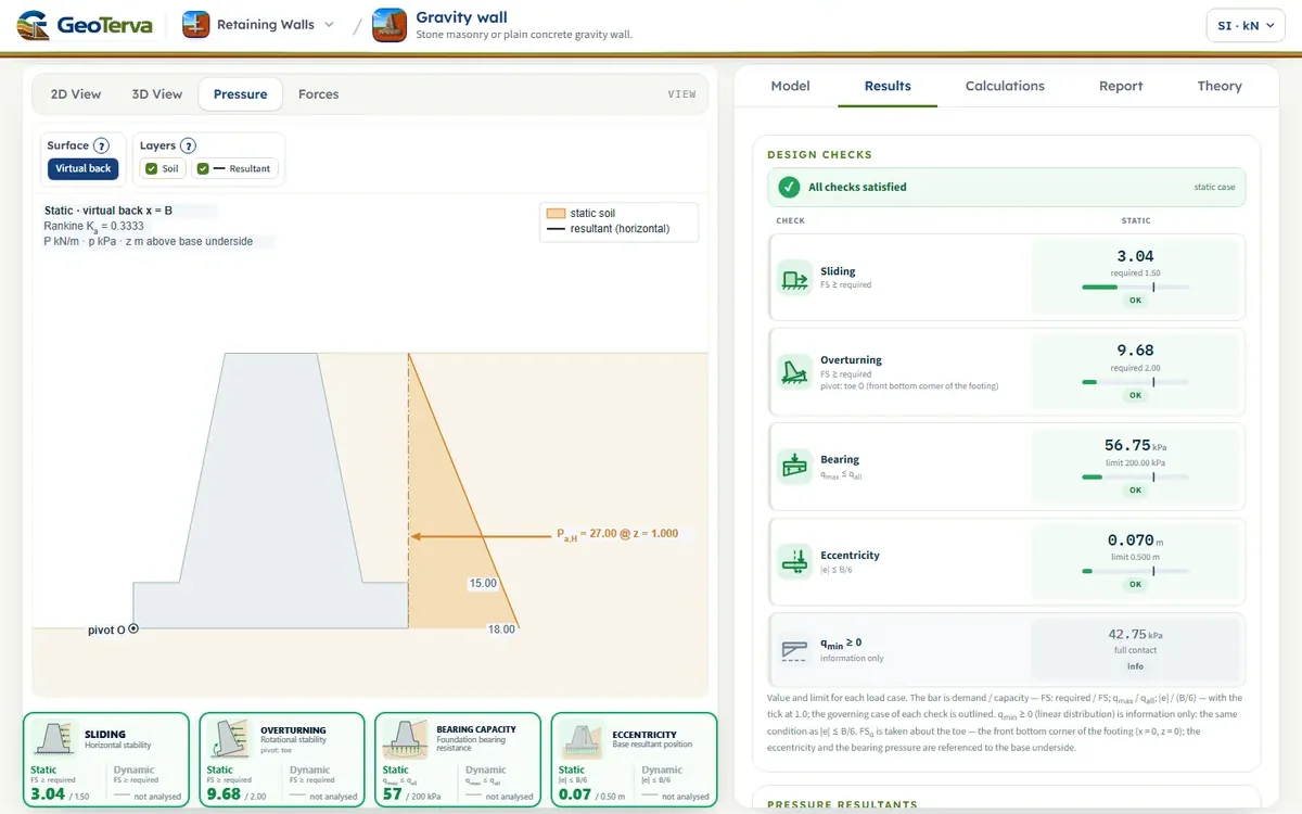
| Wall height H; top width Wu | 3.00 m; 1.00 m | Moist unit weight γ | 18.00 kN/m³ |
| Batters Wdl / Wdr | 0.50 / 0.50 m | Friction angle φ′ | 30.0° |
| Footing Wbl / Wbr; Hfl / Hfr | 0.50 / 0.50 m; 0.50 / 0.50 m | Uniform surcharge q | 10.00 kPa |
| Front ground Df; w, ηp,E, hignore | 1.00 m; 1/3, 0.00, 0.00 m | Base friction μb | 0.55 |
| Wall material | stone masonry, γm = 22.00 kN/m³ | Static method | Rankine (vertical plane at x = B) |
| Seismic | Mononobe–Okabe, kh = 0.15, kv = 0 | Required FS | static 1.50 / 2.00, seismic 1.10 / 1.10 (sliding / overturning) |
Static case
Base width and the corners of the body (origin at the toe, base underside).
Front block, front batter, core, back batter, back block.
| Part | A (m²) | W (kN/m) | x̄ (m) | z̄ (m) | W·x̄ (kN·m/m) |
|---|---|---|---|---|---|
| Front block (footing and the body above it up to H_fl) | 0.500 | 11.00 | 0.500 | 0.250 | 5.50 |
| Front batter of the body | 0.625 | 13.75 | 0.833 | 1.333 | 11.46 |
| Core of the body (top width W_u, full height) | 3.000 | 66.00 | 1.500 | 1.500 | 99.00 |
| Back batter of the body | 0.625 | 13.75 | 2.167 | 1.333 | 29.79 |
| Back block (footing and the body above it up to H_fr) | 0.500 | 11.00 | 2.500 | 0.250 | 27.50 |
| Total | 5.250 | 115.50 | 1.500 | 1.222 | 173.25 |
Flat ground: the block behind the wall is a rectangle over the back footing plus the triangle against the back batter, all moist.
φ′ = 30.0°, sin φ′ = 0.5000.
Triangle for the soil, rectangle for the surcharge; lever arms above the base underside.
Kmob, c′ = 0, hignore = 0: a triangle from the front ground to the base underside, credited in full.
Every force with its components, point of application and moment about the toe.
| Force | Fx (kN/m) | Fz (kN/m) | x (m) | z (m) | M (kN·m/m) | Used |
|---|---|---|---|---|---|---|
W_CONCRETEWall self-weight (stone masonry, body and footing) | 0.00 | −115.50 | 1.500 | 1.222 | −173.25 | SOB |
W_SOIL_HEELSoil moving with the wall (behind the body, to the vertical plane at x = B) | 0.00 | −33.75 | 2.611 | 1.889 | −88.13 | SOB |
Q_HEELSurcharge over the soil behind the wall (excluded: variable load) | 0.00 | −10.00 | 2.500 | 3.000 | −25.00 | – |
W_SOIL_TOEFront fill over the front footing (moves with the wall) | 0.00 | −4.95 | 0.276 | 0.758 | −1.36 | SOB |
PA_STATICStatic active earth pressure — soil (Rankine) | −27.00 | 0.00 | 3.000 | 1.000 | 27.00 | SOB |
PA_QSurcharge lateral pressure | −10.00 | 0.00 | 3.000 | 1.500 | 15.00 | SOB |
PP_FRONTToe passive resistance Ptoe (Kmob = 1.3333, w = 0.333) | 12.00 | 0.00 | 0.000 | 0.333 | −4.00 | S |
Moments about the toe O; the passive resistance is not used.
Seismic case
Vertical plane, δ = β = ψ = 0, kv = 0, so cos θ·cos(δ + ψ + θ) = cos²θ.
The static part keeps its shape; the increment acts at 0.6·h.
Horizontal inertia at the centroids; no vertical inertia (kv = 0).
No seismic passive coefficient.
| Force | Fx (kN/m) | Fz (kN/m) | x (m) | z (m) | M (kN·m/m) | Used |
|---|---|---|---|---|---|---|
W_CONCRETEWall self-weight (stone masonry, body and footing) | 0.00 | −115.50 | 1.500 | 1.222 | −173.25 | SOB |
W_SOIL_HEELSoil moving with the wall (behind the body, to the vertical plane at x = B) | 0.00 | −33.75 | 2.611 | 1.889 | −88.13 | SOB |
Q_HEELSurcharge over the soil behind the wall (excluded: variable load) | 0.00 | −10.00 | 2.500 | 3.000 | −25.00 | – |
W_SOIL_TOEFront fill over the front footing (moves with the wall) | 0.00 | −4.95 | 0.276 | 0.758 | −1.36 | SOB |
PAE_TOTALTotal seismic active earth pressure incl. surcharge (Mononobe–Okabe) | −48.06 | 0.00 | 3.000 | 1.288 | 61.90 | SOB |
IH_W_CONCRETEHorizontal inertia kₕ·W — wall | −17.32 | 0.00 | 1.500 | 1.222 | 21.18 | SOB |
IH_W_SOIL_HEELHorizontal inertia kₕ·W — soil behind the wall | −5.06 | 0.00 | 2.611 | 1.889 | 9.56 | SOB |
IH_W_SOIL_TOEHorizontal inertia kₕ·W — front fill | −0.74 | 0.00 | 0.276 | 0.758 | 0.56 | SOB |
The resultant moves toward the toe but stays in the middle third.
| Check | Static | Required | Seismic | Required |
|---|---|---|---|---|
| Sliding FS | 2.616 | 1.50 | 1.191 | 1.10 |
| Overturning FS | 6.256 | 2.00 | 2.819 | 1.10 |
| qmax (kPa) | 58.44 | 200.00 | 92.57 | 200.00 |
| |e| (m) | 0.068 | 0.500 | 0.401 | 0.500 |
18VariablesEvery symbol used in the tool.
19ReferencesThe three theories and the source used.
The three theories of the tool and the source whose presentation of their closed forms (Ka, Kp, KAE) the manual follows. Everything not derived from them is an assumption of this module and is marked so in the text.
- Coulomb C.A. (1776) Essai sur une application des règles de maximis et minimis à quelques problèmes de statique relatifs à l'architecture. Mémoires de l'Académie Royale des Sciences 7, Paris.
- Das B.M. (2016) Principles of Foundation Engineering, 8th ed. Cengage Learning, Boston.
- Mononobe N., Matsuo H. (1929) On the determination of earth pressures during earthquakes. Proceedings of the World Engineering Congress, Tokyo, 9:177–185.
- Okabe S. (1926) General theory of earth pressure. Journal of the Japanese Society of Civil Engineers 12(1).
- Rankine W.J.M. (1857) On the stability of loose earth. Philosophical Transactions of the Royal Society of London 147:9–27.
From theory to your own design
Check your own gravity wall in minutes
- The factors of safety for sliding and overturning, the eccentricity and the bearing pressure
- Static and seismic cases, with water, a surcharge and the passive resistance in front of the footing
- Every force in a ledger you can follow
- A clean calculation report, saved as a PDF. Online: nothing to install, no dongle, on a phone, a tablet or a PC