
On this page · 4 chapters
The vertical stress below a flexible horizontal strip load, and below an inclined one by its vertical and horizontal parts. The figures are computed from the equations.
 PDF
Lecture slides
Ready-made slides for lectures and self-study
The mechanism, the derivation, the equations and the figures of this page, in teaching order. Every slide links back to its chapter.
1Scope and assumptionsHorizontal and inclined strip loads.
Friction under a sliding footing, the thrust at the base of a retaining wall, the braking of vehicles on a road — a strip may also push along the surface. This module gives the vertical stress increase below a flexible strip carrying a uniform horizontal pressure q, and by superposition below an inclined one.
- A flexible strip of width B = 2b and infinite length; plane strain.
- The soil is a homogeneous, isotropic, linearly elastic half-space.
- Δσz is an increase caused by the load only; it may be negative (a decrease).
2The vertical stressΔσz = 4bqxz²/{π[(x² + z² − b²)² + 4b²z²]}.
As for the vertical strip, the elemental strip dr carries q dr per unit length and acts as a horizontal line load. Integrating that solution over −b ≤ r ≤ b gives
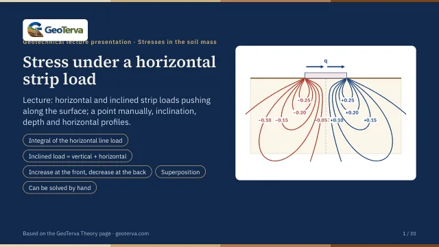
The stress is odd in x: equal and opposite at +x and −x. Ahead of the load the soil is pushed down, behind it lifted; under the centre line it is zero at every depth.
| z/b | x/b = 0.5 | x/b = 1 | x/b = 1.5 | x/b = 2 | x/b = 2.5 |
|---|---|---|---|---|---|
| 0.25 | 0.055 | 0.313 | 0.061 | 0.017 | 0.007 |
| 0.5 | 0.127 | 0.300 | 0.147 | 0.055 | 0.025 |
| 1 | 0.157 | 0.255 | 0.211 | 0.127 | 0.074 |
| 1.5 | 0.127 | 0.204 | 0.202 | 0.157 | 0.110 |
| 2 | 0.096 | 0.159 | 0.175 | 0.157 | 0.125 |
| 2.5 | 0.072 | 0.124 | 0.147 | 0.144 | 0.127 |
3Worked examplesEvery number computed by the module’s own code.
A horizontal strip. B = 4 m, q = 100 kN/m², z = 1 m, x = ±1 m; b = 2 m:
An inclined strip. The load is split into qv = q cos α and qh = q sin α; the vertical part gives the stress of the vertical strip, the horizontal part that of the horizontal strip, and the two add:
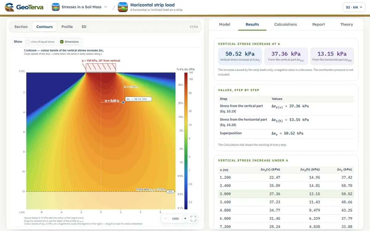
For the figure: qv = 150 cos 30° = 129.9 kN/m² and qh = 150 sin 30° = 75 kN/m²; 2x/B = ±1.5, 2z/B = 2, x/b = ±1.5, z/b = 2:
The module opens with the inclined strip at A; enter x = −2.25 m for B, or α = 90° for a purely horizontal strip. Further strips, each with its own q, inclination, width and centre line, are put in one by one with Add strip load (up to eight); the strips may not overlap — two may meet at an edge — and, the soil being elastic, the stress of each strip is found with its own x, the distance of A from its centre line, and the stresses add.
4ReferencesSources.
- Das, B.M. (2018). Principles of Geotechnical Engineering, 9th ed. Cengage Learning.
From theory to your own design
Find the stress below your own strip in minutes
- The vertical stress increase at a point below strips with a horizontal or inclined pressure
- Contours of equal stress and a depth profile
- One strip or several
- A clean calculation report, saved as a PDF. Online: nothing to install, no dongle, on a phone, a tablet or a PC