
On this page · 5 chapters
The vertical stress at any point below or beside a uniformly loaded flexible circular area: Ahlvin and Ulery's A′ + B′, computed by integrating Boussinesq's solution about the point.
 PDF
Lecture slides
Ready-made slides for lectures and self-study
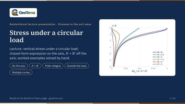
The mechanism, the derivation, the equations and the figures of this page, in teaching order. Every slide links back to its chapter.
1Scope and assumptionsOff the axis of the circle.
Directly below the centre of a uniformly loaded circle (r = 0) the stress has the closed form Δσz = q{1 − 1/[(R/z)² + 1]3/2}; the module shows it first when the point is on the axis. At any other point — under the load off its axis, under its edge, or beside it — there is no closed form; Ahlvin and Ulery (1962) evaluated the integrals and tabulated the result in two parts, A′ and B′.
- A flexible circular area of radius R with a uniform pressure q.
- The soil is a homogeneous, isotropic, linearly elastic half-space.
- The problem is axisymmetric: the stress depends on the horizontal distance r from the centre and the depth z only.
2The solutionΔσz = q(A′ + B′).
The stress is
where A′ and B′ are functions of z/R and r/R, read from the tables of Ahlvin and Ulery. The two parts come from the way the integral splits; only their sum is needed for Δσz. On the axis (r = 0) the sum reduces to the closed form above.
3How the program computes itThe integral about the point.
The program does not interpolate in the tables. It integrates Boussinesq's solution over the circle directly, in polar co-ordinates ρ, φ centred on the point below A (the figure). The load on the element ρ dρ dφ is q ρ dρ dφ and
Along each direction φ the ray crosses the loaded circle between ρ1 and ρ2 (ρ1 = 0 when A is under the load). The ρ-integral is closed:
so that
with ρ1,2 = −r cos φ ∓ √(R² − r² sin² φ). The remaining φ-integral has a smooth integrand and is summed numerically over 2880 directions. At r = 0, ρ1 = 0 and ρ2 = R for every φ, and the equation becomes the closed form above exactly.
| z/R | r/R | A′ + B′ |
|---|---|---|
| 1 | 1 | 0.33224 |
| 1 | 1.5 | 0.12664 |
| 2 | 0.4 | 0.26781 |
| 2 | 2 | 0.07334 |
| 0.5 | 0.8 | 0.64625 |
| 4 | 1.5 | 0.06487 |
4Worked exampleEvery number computed by the module’s own code.
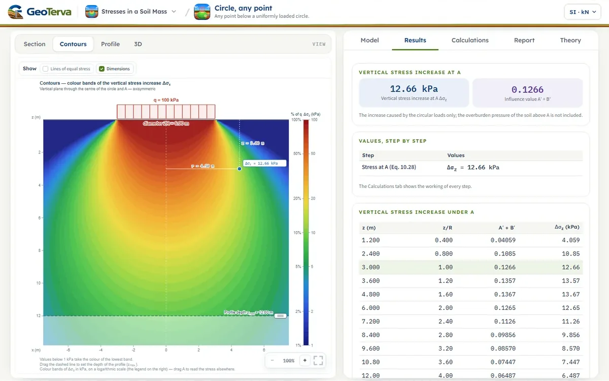
A flexible circle, R = 3 m, q = 100 kN/m². Find Δσz at the depths 1.5, 3, 4.5, 6 and 12 m (a) on the axis, r = 0, and (b) at r = 4.5 m (r/R = 1.5), i.e. outside the loaded area.
| z (m) | z/R | (a) r = 0 | (b) r = 4.5 m |
|---|---|---|---|
| 1.5 | 0.5 | 91.1 | 6.04 |
| 3 | 1.0 | 64.6 | 12.66 |
| 4.5 | 1.5 | 42.4 | 13.79 |
| 6 | 2.0 | 28.4 | 12.65 |
| 12 | 4.0 | 8.7 | 6.49 |
Outside the load the stress is small near the surface, grows to a maximum and then decreases: the load spreads sideways with depth. For r/R = 1.5 the maximum is at about z = 1.4R (4.2 m, 13.8 kN/m²); the farther out the point, the deeper the maximum lies. The module opens with part (b) at z = 3 m: Δσz = 12.66 kN/m². Further circles, each with its own q, radius and centre on the ground, are put in one by one with Add circular load (up to eight); two circles may touch but not overlap — their centres must be at least R1 + R2 apart — and, the soil being elastic, the stress of each circle is found with its own r, the distance of A from its centre, and the stresses add.
5ReferencesSources.
- Das, B.M. (2018). Principles of Geotechnical Engineering, 9th ed. Cengage Learning.
- Ahlvin, R.G. and Ulery, H.H. (1962). Tabulated values for determining the complete pattern of stresses, strains, and deflections beneath a uniform circular load on a homogeneous half space. Highway Research Bulletin 342, 1–13.
From theory to your own design
Find the stress below your own circular load in minutes
- The vertical stress increase at any point below or beside one or several circles
- Contours of equal stress and a depth profile
- Drag a circle or the point on the section
- A clean calculation report, saved as a PDF. Online: nothing to install, no dongle, on a phone, a tablet or a PC