
On this page · 11 chapters
- 1Infinite slope, and this module
- 2The idea: one strip of the mass
- 3Strength, and the factor of safety
- 4Undrained clay
- 5Water in the slope
- 6The earthquake, pseudo-static
- 7The charts
- 8Depth and angle at the required factor of safety
- 9A worked example
- 10What the module assumes, and what it does not do
- 11References
A thin sheet of soil that slides on a plane parallel to the ground, on a slope so long that its ends do not count, is the case of the infinite slope. This page explains, section by section, how the module finds the factor of safety of such a plane — the stresses a strip of the mass puts on it, the strength of the soil, the water, the pseudo-static earthquake, and the depth and the slope angle at a required factor of safety — and closes with a worked example computed by the module's own code, so that every number of that section is one the program produces.
 PDF
Lecture slides
Ready-made slides for lectures and self-study
The mechanism, the derivation, the equations and the figures of this page, in teaching order. Every slide links back to its chapter.
1Infinite slope, and this modulewhat the analysis answers
Many slope failures are shallow: a thin sheet of soil slides on a surface that runs parallel to the ground a few metres down, over a stretch of hillside so long that its ends hardly matter — a cut or fill slope in weathered soil after a wet spell, a natural slope in clay (Figure 1). The infinite slope is the model made for them. The slope is taken as infinitely long, so every part of the failure plane is in the same state and one strip of the mass stands for all of it; the balance of a strip takes a few lines.
The module finds the factor of safety of the plane at the depth you give — FS, the shear strength of the soil on the plane over the shear stress that the weight of the mass puts on it — and then turns the question round:
- the stresses behind FS: the normal stress σ and the shear stress τ from the weight, the pore pressure u, the effective stress σ′ and the strength τf;
- the depth Hreq of the plane at which the factor of safety falls to the required value, and the critical depth Hcr at which FS = 1;
- the slope angle βreq: the steepest slope that keeps the required factor of safety on the plane at the depth given;
- the effect of the water: the factor of safety of the same slope with no pore pressure and with the water at the ground surface, beside the one you enter;
- the earthquake: with a pseudo-static earthquake, the factor of safety of the earthquake case and the yield coefficient, the horizontal acceleration at which the mass starts to slide;
- charts of FS against the slope angle, the depth of the plane and the water.
One soil lies above the plane. Its strength is drained — the effective cohesion c′ and friction angle φ′ — or undrained — the strength cu with φ = 0, in total stress. The pore water is none, a water table parallel to the slope with the water flowing down it, or a pore pressure ratio ru. The factor of safety you require is an input: the module compares the result with it, and the value to ask for is yours to choose. An optional pseudo-static earthquake adds a horizontal and a vertical force to the weight of the strip.
2The idea: one strip of the massthe weight, the plane, the stresses on it
Take a strip of the mass with the length b measured along the failure plane and one metre across the slope (Figure 2). The plane lies at the vertical depth H below the ground; the strip stands on a horizontal width b cos β, so its weight is the unit weight times the volume:
The side faces are vertical. Because the slope is infinitely long and the soil the same everywhere, the forces on the two faces are equal and opposite, whatever they are, and take no part in the balance. The weight is split into a part normal to the plane and a part along it: N = W cos β and T = W sin β. Divided by the area of the plane, b × 1 m, they are the stresses the mass puts on it:
The two stresses are in the ratio τ / σ = tan β: the stress on the plane is as oblique as the slope itself, which is why the slope angle comes back in every formula below. When the soil above the plane has two unit weights — a water table above it — the total vertical stress is the sum over the two parts, σv = γ (H − hw) + γsat hw, and the two equations stay as they are.
3Strength, and the factor of safetyMohr–Coulomb on the plane, the closed forms, the critical depth
The soil on the plane can resist a shear stress τf, its strength. In a drained analysis it is the Mohr–Coulomb strength in terms of the effective normal stress — the part of the normal stress that the grains carry, what is left when the pore pressure u is taken off (Figure 3):
The factor of safety is the strength over the stress to be resisted — cohesion and friction both reduced by the same factor until the strip is just held:
With no pore pressure, σ′ = σ, and the stresses of Eq. (2) give the closed form of the factor of safety:
- Cohesionless soil (c′ = 0): FS = tan φ′ / tan β. The slope is safe as long as it is flatter than the friction angle, at any depth — the angle of repose of a dry sand or gravel.
- Soil with cohesion: FS is large for a shallow plane and falls as the plane goes deeper. A plane near the surface is held by the cohesion; a deep one only by the friction.
The critical depth, and the depth for a required factor of safety
When the slope is steeper than the friction angle, β > φ′, the friction alone cannot hold the mass, and the factor of safety falls to 1 at the depth found by putting FS = 1 in Eq. (5):
In the same way, the depth at which the factor of safety has the required value FSreq is:
and for a cohesionless soil the steepest slope that keeps FSreq is tan βreq = tan φ′ / FSreq. These are the dry forms. Where the water or the cohesion makes the factor of safety depend on the depth or the angle in a more involved way, the module solves the same equation for H or β (Section 8).
4Undrained claytotal stress, cu and φ = 0
A saturated clay loaded or cut faster than it can drain is analysed in total stress, with the undrained strength cu and φ = 0 — the short-term case of a cut in soft clay. The strength does not depend on the normal stress, so no pore pressure is entered, and the factor of safety is the strength over the shear stress of Eq. (2):
The shear stress τ = (γ H / 2) sin 2β is the largest on a slope of 45°, and FS is inversely proportional to the depth: a plane twice as deep has half the factor of safety. A clay that is stable undrained at a given depth is not necessarily stable when it has drained: the long-term state of the same slope has the pore pressures of the groundwater and the drained strength c′, φ′, and it is a drained analysis.
5Water in the slopea water table with seepage parallel to the slope, and the pore pressure ratio
Water takes strength away through the pore pressure u, which lowers the effective stress σ′ in Eq. (3). With a water table at the depth zw below the ground (measured vertically), the soil above it weighs γ and the soil below it γsat, and the height of the water over the plane is hw = H − zw (Figure 4). A table at or below the plane puts no water on it.
The water table parallel to the slope
If the water flows down the slope parallel to the ground, the equipotential through P is the line at right angles to the slope. Its length from P to the water table is hw cos β, and since the head is the same along it and the pressure at Q is zero, the pressure head at P is the rise from P to Q, that is hw cos β × cos β. So the pore pressure on the plane is:
With Eq. (9) the effective normal stress is σ′ = σ − u, and the strength and the factor of safety follow from Eq. (3) and Eq. (4). With the water table at the ground surface, hw = H and σv = γsat H, so σ′ = (γsat − γw) H cos²β = γ′ H cos²β, and:
For a cohesionless soil the factor of safety is then (γ′ / γsat) tan φ′ / tan β: since γ′ / γsat is about one half, a slope of sand or gravel that stands almost at its friction angle when dry needs a slope with half the tangent when the seepage runs parallel to its surface.
The pore pressure ratio
Where the pore pressures come from piezometers or a flow net rather than from a water table, they are given as a fraction of the weight of the soil over the plane, the pore pressure ratio:
When the effective stress is not positive
If the pore pressure is larger than the normal stress, σ′ ≤ 0: the water would lift the soil off the plane, no friction can act, and the module takes the strength as the cohesion alone and says so. The input needs another look — a pore pressure ratio that high belongs to a much steeper or much wetter state than the one analysed.
6The earthquake, pseudo-statica horizontal and a vertical force on the strip, and the yield coefficient
The module can add an earthquake in the pseudo-static way: the shaking is replaced by a steady acceleration, a fraction of g, applied to the mass over the plane. The strip of Figure 2 then carries, besides its weight W, a horizontal force kh W acting down the slope and a vertical force kv W, upward or downward (Figure 5). kh and kv are the coefficients you give: the module applies them and takes none from a code.
Per unit area of the plane the weight is W / A = σv cos β. A vertical acceleration upward lightens the mass, (1 − kv) W / A; one downward adds to it, (1 + kv) W / A; the horizontal force is kh W / A. Adding the forces and splitting the resultant on the normal and on the tangent of the plane gives the stresses of the earthquake case:
The pore pressure is the static one: the shaking adds none, so σ′ = σ − u with the u of the static water, and the factor of safety of the earthquake case is FSeq = τf / τ with the new σ and τ. The horizontal force lowers the normal stress and raises the shear stress on the plane, so the friction falls while the load grows. If σ′ is no longer positive, the friction is taken as zero and the cohesion alone is kept, as in the static case.
Which way the vertical force acts
The module tries the vertical force upward and downward and keeps the direction that gives the lower factor of safety; it says which it was. In a soil with friction it is usually the upward one: it lightens the mass and takes some of the normal stress with it. In a clay in total stress the strength cu does not depend on the normal stress, so it is the downward force, which raises the shear stress, that governs.
The yield coefficient
The yield coefficient ky is the horizontal coefficient at which the factor of safety falls to 1, with kv as given. For a dry cohesionless soil and kv = 0 it follows from putting FSeq = 1 in the stresses above:
In every other case — with cohesion, with water, with kv — the module finds it by raising kh from zero until FS = 1. A shaking that stays below ky g does not start the mass; one above it does, and how far the mass then moves is a question for a sliding-block analysis, which the module does not do.
7The chartshow the factor of safety changes with the slope, the depth and the water
The Charts tab draws the factor of safety against the slope angle, against the depth of the plane and against the water (its depth, the ratio ru, or cu), with the other inputs as entered, and the strength line with the point of the plane on it. Figure 6 is the worked slope of Section 9:
- Against the slope angle the factor of safety falls steadily; the distance between the curves shows how much of the margin the water takes. The slope angle at which a curve crosses FSreq is βreq.
- Against the depth the curve of a soil with cohesion falls from a large value at the surface to a level set by the friction, and where it crosses FS = 1 is the critical depth. A water table puts its mark at the depth where the water first reaches the plane: above it the curve of the dry soil is followed.
- Against the water, the factor of safety rises as the water table goes deeper and falls as ru grows; this shows how much a drained slope depends on a pore pressure that is hard to know.
With a pseudo-static earthquake every chart carries the earthquake case as a second, orange line and the ring of the model appears twice (red: static, orange: earthquake). A fifth chart gives the factor of safety against kh, with the yield coefficient where the line crosses FS = 1.
8Depth and angle at the required factor of safetywhat the Results tab reports, and how
The Results tab gives, beside the factor of safety and the comparison with the required value:
- Hreq — the depth of the plane at which FS falls to FSreq, at the slope angle given. It is the first depth, going down from the ground, where the requirement is lost; where the factor of safety never falls to it, the card says no limit.
- βreq — the steepest slope angle, going up from the flat, at which FSreq is still reached on the plane at the depth given; above 70° when it is reached at every angle the module takes.
- Hcr — the critical depth, where FS = 1. There is none when the factor of safety stays above 1 at every depth, as in a slope flatter than φ′.
- FS without pore pressure and with the water at the ground surface — the same slope, soil and depth with the water changed, shown when the model has water; they bracket the result.
- FSeq and ky — with a pseudo-static earthquake, the factor of safety of the earthquake case against its own required value and the yield coefficient; Hreq,eq and βreq,eq are the depth and the angle at which the earthquake case reaches that value (Section 6).
The Calculations tab writes each step with its equation and the numbers of this model, and the closed forms beside the stresses; Hreq, βreq and Hcr are written in closed form where there is one (Eq. (7), Eq. (6)) and are found by solving the factor of safety for the depth or the angle where there is not.
9A worked exampleevery number computed by the module's own code
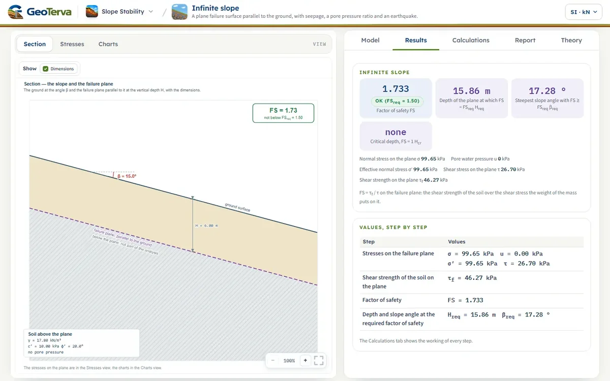
The model the Model tab opens with: a slope of15°, a plane at a vertical depth of 6 m, a soil with γ = 17.8 kN/m³, c′ = 10 kPa and φ′ = 20°, and no pore pressure. Every number below is computed by the module's own code as this page opens.
The stresses and the factor of safety
The same number from the closed form Eq. (5): the cohesion term is 0.3745 and the friction term tan 20° / tan 15° = 1.3584, and they add to 1.7329.
The depth for a factor of safety of 2
The same slope with other water
| Case | σv (kPa) | σ (kPa) | u (kPa) | σ′ (kPa) | τ (kPa) | τf (kPa) | FS |
|---|---|---|---|---|---|---|---|
| No pore pressure | 106.8 | 99.6 | 0.0 | 99.6 | 26.7 | 46.3 | 1.73 |
| Water table 2 m below the ground, the water flowing parallel to the slope | 113.6 | 106.0 | 36.6 | 69.4 | 28.4 | 35.3 | 1.24 |
| Water table at the ground surface, flowing parallel to the slope | 117.0 | 109.2 | 54.9 | 54.2 | 29.2 | 29.7 | 1.02 |
| Pore pressure ratio ru = 0.25 | 106.8 | 99.6 | 26.7 | 72.9 | 26.7 | 36.6 | 1.37 |
| Undrained clay, cu = 40 kPa (total stress) | 106.8 | 99.6 | 0.0 | 99.6 | 26.7 | 40.0 | 1.50 |
| Pseudo-static earthquake, kh = 0.15, kv = 0.05, no pore pressure | 106.8 | 90.7 | 0.0 | 90.7 | 40.3 | 43.0 | 1.07 |
The water takes the factor of safety from 1.73 to 1.24 with the table 2 m below the ground — it adds weight below the table and pore pressure at the plane — and to 1.02 with the water at the ground surface, hardly above the limit. A pore pressure ratio of 0.25 gives 1.37, and the undrained clay 1.50. The slope that has a comfortable factor of safety dry has none when it is wet: this is why the module shows the factor of safety dry and with the water at the surface beside the result. The pseudo-static earthquake of the last row takes the dry slope from 1.73 to 1.07 (the upward vertical force governs), and the horizontal coefficient that brings the factor of safety to 1 is ky = 0.175.
10What the module assumes, and what it does not dothe assumptions and the limits in one place
Every calculation rests on assumptions. The module sorts them by how they reach the results:
- The model — an infinitely long slope: the ground is a plane, the failure surface a plane parallel to it at the vertical depth H, and the ends of the sliding mass play no part. Every part of the plane is in the same state; the analysis is two-dimensional, one metre across the slope.
- The soil — one soil above the plane, with the strength and the unit weight given. Layers, a soil that changes along the slope or with depth, and a strength that grows with depth are not in this model; a failure plane at the contact of a weak layer is analysed with the properties of that layer for the whole mass, if that is the case at hand, or in the Slope Stability module.
- The water — a water table parallel to the slope with the water flowing down it parallel to the ground, so that u = γw hw cos²β; or the pore pressure ratio ru. No other flow pattern is analysed, and the pore pressure is not computed from rainfall or from the permeability of the soil.
- The strength — Mohr–Coulomb in effective stress, drained, or cu with φ = 0 in total stress. Where the effective stress on the plane is not positive, the friction is taken as zero and the cohesion kept. Residual strength, progressive failure and the effect of roots are not modelled; a strength for a slope that has slid before is an input like any other.
- The earthquake — pseudo-static only: a steady horizontal and vertical acceleration, as fractions of g, on the weight over the plane. The shaking adds no pore pressure; its amplification, its duration, the excess pore pressure of a loose saturated soil and the permanent displacement are not analysed. The coefficients are the engineer's; none is taken from a code.
- What is not included — a surcharge, a tension crack, reinforcement, a wall at the toe. The factor of safety is that of one plane at one depth; the critical depth and the charts show how it changes with the depth, but the module does not look for a weaker plane that is not parallel to the ground.
An infinite slope is the right model for a shallow slide in a long, uniform slope. Where the slope is short compared with the depth of the plane, or the soil or the water change along it, the ends matter and the factor of safety of this model is not the one of the slope; the Slope Stability module, which cuts a mass of any shape into slices, is the tool for that.
11Referencesthe infinite slope, the pore pressure ratio and the yield coefficient
- Das, B.M. (2018). Principles of Geotechnical Engineering, 9th ed. Cengage Learning, Boston. Chapter 15, Slope Stability: the infinite slope in Sections 15.2–15.4.
- Skempton, A.W. and DeLory, F.A. (1957). Stability of natural slopes in London Clay. Proceedings of the 4th International Conference on Soil Mechanics and Foundation Engineering, London, 2, 378–381.
- Bishop, A.W. and Morgenstern, N.R. (1960). Stability coefficients for earth slopes. Géotechnique, 10(4), 129–150.
- Duncan, J.M., Wright, S.G. and Brandon, T.L. (2014). Soil Strength and Slope Stability, 2nd ed. Wiley, Hoboken.
- Newmark, N.M. (1965). Effects of earthquakes on dams and embankments. Géotechnique, 15(2), 139–160.
From theory to your own design
Find the factor of safety of your own slope in minutes
- The factor of safety against the required value, static and with the earthquake
- The depth and the slope angle at the required factor of safety, and the critical depth
- Charts of the factor of safety against the angle, the depth, the water and the earthquake
- A clean calculation report, saved as a PDF. Online: nothing to install, no dongle, on a phone, a tablet or a PC