
On this page · 16 chapters
- 1The braced cut and its members
- 2Why the pressure is not Rankine’s
- 3Apparent pressure from measured strut loads
- 4The envelope for sand
- 5Water and a surcharge
- 6Struts: from the envelope to the strut loads
- 7Sheet piles
- 8Wales
- 9The members as they are given
- 10Verifying the steel to EN 1993-1-1
- 11Verifying the steel to AISC 360-22
- 12The envelopes against real cuts
- 13The base of a cut in sand: piping
- 14What the method assumes, and what it leaves out
- 15Worked example
- 16References
A braced cut is held open by struts pressing on the sheeting from both sides, not by embedment below the base. This page follows the source section by section — the apparent-pressure envelopes, a sand in several layers, water and a surcharge, the design of the struts, the sheet piles and the wales, the case studies and the stability of the base against piping — and then the verification of the steel members, with every figure drawn from the same numbers the module uses.
 PDF
Lecture slides
Ready-made slides for lectures and self-study
The mechanism, the derivation, the equations and the figures of this page, in teaching order. Every slide links back to its chapter.
1The braced cut and its membersSoldier beams or sheet piles, wales and struts.
Deep excavations with vertical faces — the basement of a building in a built-up street, a cut-and-cover tunnel — are held open by a temporary bracing system, which keeps the ground behind the face from failing and, with it, the settlement or the loss of bearing of the foundations nearby. Two arrangements are common. In the first, vertical soldier beams of steel or timber are driven before digging starts, and horizontal timber lagging is placed between them as the excavation goes down. In the second, interlocking sheet piles are driven first to form a continuous wall. In both, horizontal wales are fixed along the face at each strut level as soon as the excavation reaches it, and struts — horizontal steel members in compression — cross the cut from wale to wale.
To choose the struts, the wales and the sheeting, the engineer needs the lateral pressure the bracing will receive. Theory gives the total thrust on the wall, but not how it is distributed down the wall: that depends on the soil, on the sequence and the speed of the work, on the crew and on the equipment. The design pressures are therefore empirical envelopes, drawn around the pressures back-figured from the strut loads measured on real cuts.
This module is for a cut with vertical walls braced by horizontal struts at any number of levels, in sand — one layer, or several layers reduced to one active-pressure coefficient — with or without a water table above the base and a surcharge beside the cut. Anchored and raking supports, the deflection of the wall and the settlement of the ground behind it are separate subjects, not part of this calculation.
2Why the pressure is not Rankine’sThe wall rotates about its top.
A cantilever retaining wall yields by rotating about its base, and Rankine’s active pressure — zero at the top, largest at the bottom — describes it well. A braced wall moves the other way. The first strut goes in while the cut is still shallow, and from then on the top of the wall hardly moves. Each deeper lift is dug before its strut is installed, and the time between the two grows with the depth, so the wall bends in progressively lower down: at the end of the excavation it has rotated about its top.
Three things follow for the pressure. Near the top it stays close to the at-rest value, because the soil there has barely moved. Near the base it can fall below the Rankine active value, because the soil there has moved far past the state of plastic equilibrium. And the resultant thrust Pa acts higher up the wall than the third point of a triangle — at naH above the base, with na greater than 1/3.
The magnitude of that thrust can be found by the general wedge theory. A trial failure surface behind the wall is taken as an arc of a logarithmic spiral, and the wedge it cuts off is balanced by moments about the pole of the spiral:
Every radius of this spiral meets the curve at φ′ to its normal, so the resultant of the normal and friction forces on the surface passes through the pole and drops out of the moment equation. What remains is the weight W of the wedge, the adhesion Ca = c′aH on the wall, the moment MC of the cohesion along the spiral, and the thrust P itself, inclined at δ′ to the normal of the wall:
Repeating the trial for several surfaces gives the largest P, the active thrust Pa. For a granular soil it comes out some 15 to 20 per cent above Coulomb’s value for a similar wall. But the analysis still says nothing about how the pressure is distributed down the wall, and na depends on factors that belong to the soil and to the site. That is why braced cuts are designed from envelopes instead.
3Apparent pressure from measured strut loadsHow the envelopes were made.
The pressure in a braced cut changes from place to place, and every strut should be designed for the largest load it may meet. The envelopes are built for exactly that. On an instrumented cut the load in each strut is measured, and dividing it by the area of wall that strut serves — the horizontal spacing s times half the distance to the strut above plus half the distance to the strut below — turns it into an apparent pressure over that band:
with d1 the depth of the first strut and di the distances between the following ones. A diagram drawn around all the diagrams obtained this way, cut after cut, is an apparent-pressure envelope.
Peck built envelopes in this way from the strut loads observed in the subway cuts of Berlin, Munich and New York for sand, and in the same manner for soft to medium and for stiff clays. An envelope is therefore not the pressure on the wall at any one time; it is drawn so that the load taken from it for a single strut is on the safe side of the loads that were measured.
4The envelope for sandσₐ = 0.65 γH Kₐ over the full height.
For sand, Peck’s envelope is a rectangle: one pressure over the whole height of the cut, 65 per cent of the largest ordinate of the Rankine active triangle.
γ is the unit weight of the sand, H the depth of the cut, Ka the Rankine active coefficient and φ′ the effective friction angle. For comparison the two clay envelopes are drawn beside it; their shape is set by the stability number γH/c.
Where the envelopes apply
The source lists four conditions that come with the envelopes:
- they apply to excavations deeper than about 6 m (20 ft);
- they assume the water table below the bottom of the cut;
- sand is taken as drained, with zero pore-water pressure;
- clay is taken as undrained, and its pore-water pressure is not considered.
A sand in several layers
The envelope needs one Ka, and the source gives no rule for a profile of several sands. Three are in use, and they do not agree, because Ka is a convex function of φ′ — an average taken inside the curve lands below it:
5Water and a surchargeAdded beside the envelope, never inside it.
The envelopes assume the water table below the base and no load on the ground beside the cut. The module adds both, each as its own diagram beside the envelope, so the envelope itself is never scaled beyond what it was measured for.
Water above the base
Peck’s sand envelope is an effective-stress diagram. With the water table inside the depth of the cut, the overburden at the base is taken effective — the moist unit weight above the table, the submerged one below it — and the water pushes on the sheeting separately, with its full head:
The first sum runs over the layers above the water table, the second over those below it. This is the usual treatment of a drained sand: the grains push with their buoyant weight, the water with its full hydrostatic head, and the struts carry both.
A surcharge beside the cut
The envelopes were assembled from cuts without a surface load, so a surcharge q is not folded into them — that would put the empirical 0.65 on it as well. It is carried as its own uniform pressure over the full height:
6Struts: from the envelope to the strut loadsThe source’s steps; P = R s.
Struts are horizontal columns: they carry the pressure of the wall along their axis and are bent by their own weight. Their capacity depends on their slenderness, which intermediate vertical and horizontal supports reduce, and in wide cuts they may have to be spliced. In construction work the struts should be at least about 2.75 m (9 ft) apart vertically.
For the loads, the source gives a simplified and conservative procedure, which designers vary in detail:
- Draw the pressure envelope and the strut levels. The sheeting is taken as hinged at every strut level except the top and the bottom ones; many designers instead take it as hinged at every level except the top.
- Split the wall at the hinges into simple cantilevers at the ends and simple beams between them, and find the reactions of each piece by statics — A, B1, B2, C1, C2 and D in a four-strut cut.
- The load of each strut is the sum of the reactions it receives, times the horizontal spacing s.
- With the load of each level and the bracing conditions known, choose the sections.
Every piece is statically determinate: two supports carry it, and the moment equation about one of them together with the balance of horizontal forces gives both reactions. A strut at a hinge belongs to the pieces on both sides, which is why it collects two reactions. The reactions are forces per unit length of the wall; the strut spacing turns them into strut loads. In the worked example at the end of this page they come out as A = 110.18, B1 = 22.04, B2 = 35.26, C = 70.52 kN/m.
7Sheet pilesThe largest moment and the modulus it asks for.
The sheet piles are designed from the same pieces. For each piece the largest bending moment is found — where the shear force changes sign, inside a span or at a strut where a cantilever meets it — and the largest of those is the design moment, per unit length of the wall. The required section modulus follows from the allowable flexural stress of the sheet-pile steel, and a section with at least that modulus is chosen from a table of sheet piles:
8WalesA simple span s between struts: R s²/8.
Wales spliced properly may be treated as continuous along the wall. Conservatively they are taken as pinned at the struts: a simple span s loaded by the reaction of its level per unit length of the wall, so that at each level
and the required section modulus follows as S = Mmax/σall. The level with the largest reaction governs. Wales are sometimes fastened to the sheet piles at points chosen to give them the lateral support they need.
9The members as they are givenA steel grade and a section, by its numbers or from the catalogue.
The source sizes the members with an allowable stress and a table of sections. The module goes one step further and checks each member as it will be built. Every member — the sheeting, the wale and the strut — carries its own steel grade, and the grade hands over the yield strength and nothing else:
| Grade | fy (MPa), t ≤ 40 mm | fy (MPa), 40 < t ≤ 80 mm | ε = √(235/fy) |
|---|---|---|---|
| S235 | 235 | 215 | 1.00 |
| S275 | 275 | 255 | 0.92 |
| S355 | 355 | 335 | 0.81 |
The section is given the way a profile table gives it. The sheeting is given by its section modulus per metre of wall, since sheet piles are chosen from the maker’s tables. The wale is given by its section modulus about the axis it bends about, or as an IPE, HEA, HEB, HEM or UPN from the catalogue, or as a steel box. The strut is given by its area and its second moment of area about the weak axis — the two numbers its checks need — or as a round, square or rectangular tube or a rolled section from the catalogue.
A table prints two section moduli, and a modulus given by its number must say which of them it is:
Whichever way a member is given, the calculation also prints what the load asks of it — the number to look a table up with:
10Verifying the steel to EN 1993-1-1Design actions, classes, bending and shear, buckling.
EN 1993-1-1 — one of the two design codes of the module — verifies each member against a resistance built from the yield strength and the partial factors. The loads that come off the envelope are working values — Peck’s envelope is an upper bound of measured loads — and they are raised once to design values:
| Action | Factor | Set A1 | Set A2 | |
|---|---|---|---|---|
| Permanent | unfavourable | γG | 1.35 | 1.0 |
| favourable | γG | 1.0 | 1.0 | |
| Variable | unfavourable | γQ | 1.5 | 1.3 |
| favourable | γQ | 0 | 0 |
| Factor | resistance of | EN 1993-1-1 | EN 1993-5 (piling) |
|---|---|---|---|
| γM0 | a cross-section, any class | 1.00 | 1.00 |
| γM1 | a member to instability (buckling) | 1.00 | 1.10 |
| γM2 | a cross-section in tension, to fracture | 1.25 | 1.25 |
The class of the cross-section
Whether a section can reach its plastic moment, or buckles locally first, is set by the slenderness of its walls — c/t against limits in ε:
| Part | class 1 | class 2 | class 3 |
|---|---|---|---|
| internal part, in compression | 33ε | 38ε | 42ε |
| internal part, in bending | 72ε | 83ε | 124ε |
| outstand flange, in compression | 9ε | 10ε | 14ε |
| tube, d/t | 50ε² | 70ε² | 90ε² |
Bending: the sheeting and the wale
For the sheeting EN 1993-5 applies the same resistance to a unit width of wall, and reduces the modulus of a wall of single or double U-piles by a factor βB where the interlocks on the neutral axis may slip; its value is set by the National Annex, and it is 1.0 for Z-piles.
Shear in the wale
Av is the shear area: for a rolled I-section A − 2btf + (tw + 2r)tf, never less than the web itself; for a rectangular tube Ah/(b + h). Above half the plastic shear the web cannot carry its full share of the moment, and the plastic modulus is reduced:
The reduction is written on the plastic modulus, so it applies to a class 1 or 2 section; past Vpl,Rd the section has already failed in shear and no reduction is made. The compression flange of a wale bears against the sheeting along its whole length, so lateral-torsional buckling is not the governing mode.
The strut: squashing and flexural buckling
A strut buckles about its weak axis, so I is the smaller second moment of area and Lcr = K Lb the effective length — the clear width of the cut unless a king post or a cross brace holds the strut in between. The imperfection factor α comes from the buckling curve of the section:
| Section | Curve | α |
|---|---|---|
| hot-finished tube (EN 10210), up to S420 | a | 0.21 |
| hot-finished tube, S460 | a0 | 0.13 |
| cold-formed tube (EN 10219) | c | 0.49 |
| rolled I or H, h/b > 1.2, tf ≤ 40 mm | b | 0.34 |
| rolled I or H, h/b > 1.2, 40 < tf ≤ 100 mm | c | 0.49 |
| rolled I or H, h/b ≤ 1.2, tf ≤ 100 mm | c | 0.49 |
| rolled I or H, tf > 100 mm | d | 0.76 |
| channel (UPN) | c | 0.49 |
For the cut the module opens with, the largest strut load is P = 318.75 kN, so NEd = 1.35 × 318.75 = 430.31 kN. With the strut the Sections stage starts from — A = 65.7 cm², I = 3598 cm⁴, fy = 275 MPa, curve c — over Lcr = 6.00 m the chain runs Ncr = 2071.5 kN, λ̄ = 0.9339, Φ = 1.1159, χ = 0.5791, Nc,Rd = 1806.8 kN and Nb,Rd = 1046.4 kN: buckling governs, and NEd/NRd = 0.411.
11Verifying the steel to AISC 360-22LRFD or ASD; classes, flexure and shear, the column curve.
AISC 360-22, the second design code of the module, verifies each member against a nominal strength Rn from its provisions for compression, flexure and shear. The method is chosen on the Analysis settings stage: by LRFD the load is factored and the strength reduced by φ; by ASD the working load is compared with the strength divided by the safety factor Ω.
The loads that come off the envelope are taken as the lateral earth pressure H of ASCE 7-22. It enters the LRFD combinations with a load factor of 1.6 where it adds to the load effect — as it always does on the bracing of a cut — and the ASD combinations with 1.0:
| Limit state | section | φ (LRFD) | Ω (ASD) |
|---|---|---|---|
| compression | every section | 0.90 | 1.67 |
| flexure | every section | 0.90 | 1.67 |
| shear | rolled I-shape, h/tw ≤ 2.24√(E/Fy) | 1.00 | 1.50 |
| shear | channels, hollow and box sections | 0.90 | 1.67 |
The elements of the section
Before a strength is computed, the flange and the web are classed by the slenderness of their walls, b/t or h/tw, against limits in √(E/Fy) — Table B4.1a in compression (nonslender or slender), Table B4.1b in flexure (compact, noncompact or slender):
| Part | ratio | compression λr | flexure λp | flexure λr |
|---|---|---|---|---|
| flange of a rolled I | bf/2tf | 0.56√(E/Fy) | 0.38√(E/Fy) | 1.0√(E/Fy) |
| flange of a channel | bf/tf | 0.56√(E/Fy) | 0.38√(E/Fy) | 1.0√(E/Fy) |
| web of an I or a channel | h/tw | 1.49√(E/Fy) | 3.76√(E/Fy) | 5.70√(E/Fy) |
| wall of a rectangular hollow section | b/t | 1.40√(E/Fy) | 1.12√(E/Fy) flange, 2.42√(E/Fy) web | 1.40√(E/Fy) flange, 5.70√(E/Fy) web |
| round tube | D/t | 0.11 E/Fy | 0.07 E/Fy | 0.31 E/Fy |
Flexure: the sheeting and the wale
The wale is held laterally along its whole length by the sheeting its compression flange bears against, so Lb = 0 and lateral-torsional buckling is not a limit state. A compact section reaches its plastic moment:
A noncompact flange of an I-section falls linearly from Mp to 0.7FySx as λ goes from λp to λr:
A rectangular hollow section with a noncompact flange or web and a round tube follow provisions of their own. The sheeting and a wale given by their modulus are taken at the strength the modulus claims — Fy Z for a compact section, Fy S at first yield.
Shear in the wale
For a rolled I-shape with h/tw ≤ 2.24√(E/Fy) — every rolled section of the catalogue — Cv1 = 1.0 and φv = 1.00. Unlike EN 1993-1-1, AISC 360-22 does not reduce the moment strength of a beam for the shear it carries.
The strut: flexural buckling
One column curve serves every section — there are no buckling curves to choose, as there are in EN 1993-1-1. r is the smaller radius of gyration and Lc = K Lb the effective length, the clear width of the cut unless a king post or a cross brace holds the strut in between. The specification recommends Lc/r ≤ 200.
For the cut the module opens with, the largest strut load is P = 318.75 kN. By LRFD Pu = 1.6 × 318.75 = 510.00 kN. With the strut the Sections stage starts from — Ag = 65.7 cm², r = 7.40 cm, Fy = 275 MPa — over Lc = 6.00 m the chain runs Lc/r = 81.1, Fe = 300.3 MPa, Fcr = 187.4 MPa, Pn = 1231.5 kN and φcPn = 1108.3 kN: Pu/φcPn = 0.460. By ASD the same strut has Pn/Ωc = 737.4 kN against Pa = 318.75 kN, a ratio of 0.432.
12The envelopes against real cutsBoston and Chicago, from the case studies.
The procedure is straightforward once an envelope is chosen, and choosing it is the hard part. Two instrumented cuts show how much judgment that takes.
Boston: the subway extension
Three test sections of a subway extension in Boston were instrumented. At test section B the cut was 58 ft (17.7 m) deep, through some 26 ft of gravel, sand, silt and clay fill, an organic silt, and a layer of sand and gravel with some clay over rock, braced at five levels with the struts 12 ft (3.66 m) apart. The envelopes exist for sand and for clay only, so the profile was bracketed with both. As a sand, with γ = 114 lb/ft³ and Ka = 0.26, σa = 0.65γHKa = 1117 lb/ft² (53.5 kPa); as a soft to medium clay with c = 890 lb/ft², σa = γH[1 − 4c/γH] = 3052 lb/ft² (146.1 kPa).
The measured loads differed widely from both predictions, mainly because the soil parameters were uncertain, and the loads the struts were actually designed for were well above those measured.
Chicago: the National Plaza
The south half of the National Plaza in Chicago needed a cut 70 ft (21.3 m) deep, braced at six levels, through 13 ft of sand fill over clays of increasing strength. To compare Peck’s envelope with the wale loads measured, the profile is converted to one equivalent clay: the clays first by thickness, then that clay together with the sand. The module’s own conversion gives cav = 729 lb/ft² (34.91 kPa) and γav = 125.8 lb/ft³ (19.76 kN/m³); γavH/cav = 12.08 is above 4, so the soft-to-medium envelope applies with σa = 5889 lb/ft² (282.0 kPa).
Peck’s envelope turned out to give about 1.8 times the pressure actually observed. That is not surprising: an envelope drawn around many cuts in many places is conservative for any one of them, and experience with similar soils on a site can reduce the over-design substantially.
13The base of a cut in sand: pipingThe exit gradient against the critical gradient.
The bottom of a cut in sand is generally stable, and it stays so while the water inside the excavation stands no lower than the groundwater outside. Once the cut is dewatered, water flows under the sheeting and up through the base, and where it leaves the ground a high upward gradient can lift the grains — the base boils, or pipes. To check it, a flow net is drawn for the cut and the largest exit gradient next to the wall is read from it:
h is the loss of head across the net, Nd the number of drops, and a the length of the flow element where the water leaves the ground beside the wall. The factor of safety compares it with the critical gradient of the sand:
icr lies between 0.9 and 1.1 for most soils, 1 on average, and a factor of safety of about 1.5 is desirable.
Harr’s theoretical solution
For a sheeted excavation in sand that extends to a great depth, the exit gradient has been solved theoretically, and the source gives the result as two charts. The first gives a modulus m from 2L2/B (or B/2L2) and 2L1/B, with L1 the depth of the saturated sand outside the sheeting down to the level of the base and L2 the embedment of the sheeting below it; the second gives L2iexit(max)/h from m and 2L1/B. With L2 and h known:
Model tests of the same question are summarised as charts of the factor of safety against heave in loose sand and against piping in dense sand, for sand to a great depth and for an impervious layer at limited depth below the base.
14What the method assumes, and what it leaves outThe limits of the envelopes; wall movement and settlement.
What the calculation rests on, in one place:
- The envelopes were assembled from cuts deeper than about 6 m; a shallower cut lies outside the data they summarise, and the module notes it.
- They assume the water table below the base. This module keeps the sand envelope on the effective overburden and adds the hydrostatic pressure beside it when the table is higher; seepage into the cut is checked at the base.
- An envelope is not the real pressure on the wall at any one time. It gives safe strut loads; it does not give the deflection of the wall.
- The sheeting is idealised as a chain of determinate beams, hinged at the chosen strut levels; its own stiffness and the embedment below the base are not used.
- The wales are simple spans between the struts, the safe side for a wale that runs continuously past several of them.
- The steel is verified to EN 1993-1-1; class-4 sections are not designed, and the lateral-torsional buckling of the wales is not checked.
Lateral yielding of the wall, and settlement
Some lateral movement of the sheeting is to be expected. How much depends above all on the time between digging a lift and installing its wales and struts. Sheet piles are often driven below the base to reduce the yielding in the last stages of the excavation: with deep clay below the cut this helps considerably while γH/c is below about 6, but little when it is about 8, when large yielding and even the collapse of the bracing can follow; where a hard layer lies below the clay, the piles should be embedded in it.
The yielding of the wall lets the ground around the cut settle — the ground loss. Published curves give the settlement to be expected in different soils, a general guide only. From about 150 case histories, mostly in soft clay, the largest settlement averages about 1.1 per cent of the depth of the cut in soft clay, 0.2 per cent in stiff clay and 0.3 per cent in non-cohesive soils, usually within half the depth of the cut from the wall; the largest horizontal deflection of the wall in soft clay averaged about 0.9 per cent of the depth.
15Worked exampleEvery number computed by the module’s own code.
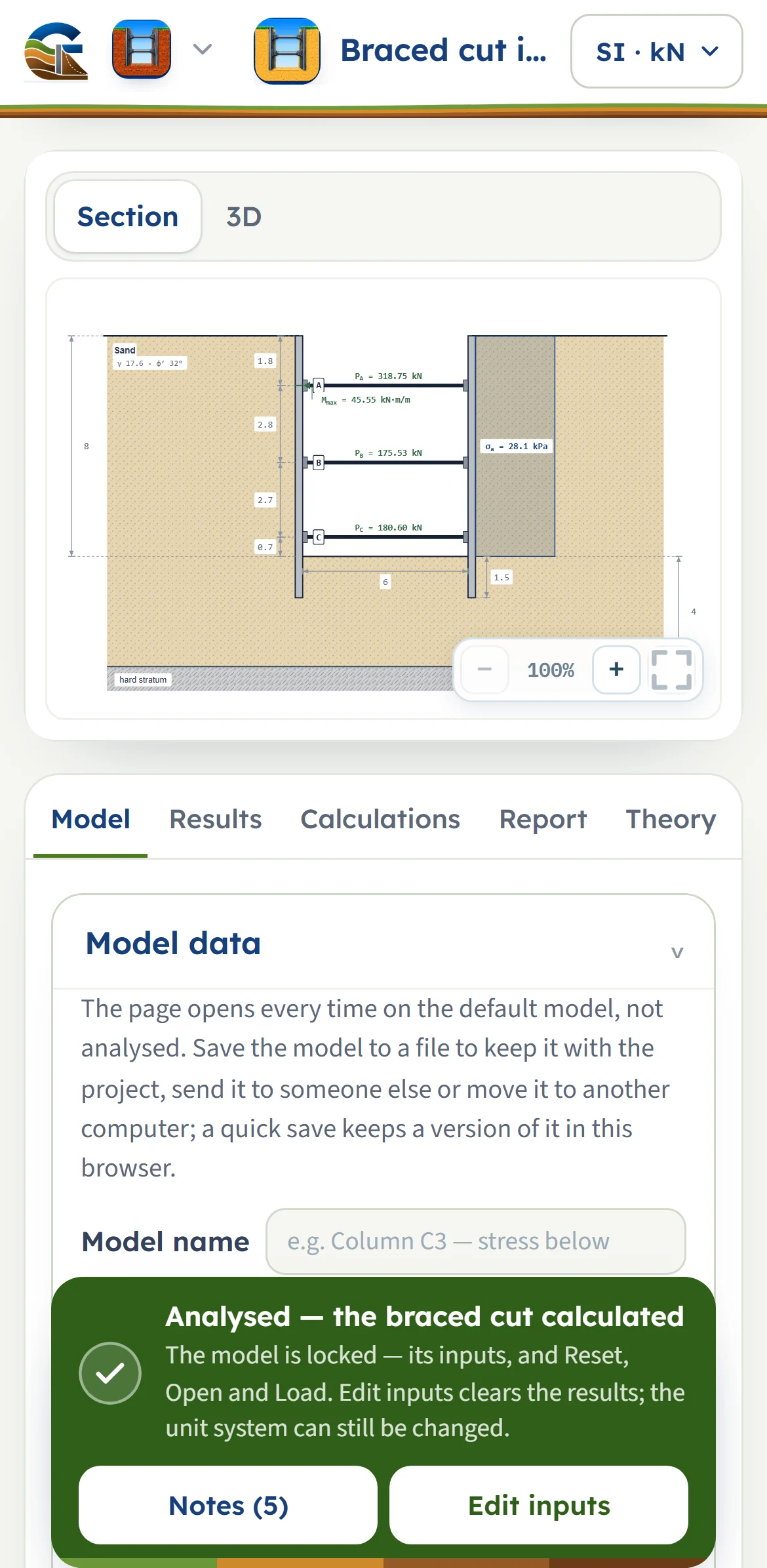
One cut in sand is worked through here, from the envelope to the section moduli: a cut 27 ft deep in a sand with γ = 112 lb/ft³ and φ′ = 32°, struts at 6, 15 and 24 ft below the surface and 12 ft apart in plan, the sheeting hinged at the interior strut, and an allowable stress of 24 kip/in². The module runs it in SI.
The envelope
The strut loads
With the hinge at B the wall is two pieces: A–B with the cantilever above A, and B–C with the cantilever below C. Their reactions, per metre of wall:
The sheet piles
The largest moment is over strut A, at the root of the cantilever:
The wales
The largest reaction is at level A, so that wale governs:
To EN 1993-1-1 in S275, with γF = 1.35, the same moments ask for Wreq = 237 cm³/m for the sheeting and 904 cm³ for the wale at level A.
Piping, by Harr’s charts
The base is checked for a sheeted cut in deep sand with h = 4.5 m, L1 = 5 m, L2 = 4 m and B = 5 m. Then 2L1/B = 2 and B/2L2 = 0.625; the first chart gives m ≈ 0.033, and the second, for that modulus, L2iexit(max)/h = 0.54. With icr = 1:
The cut the module opens with, verified to EN 1993-1-1
The module opens with a cut 8.00 m deep and 6.00 m wide, struts at 1.80, 4.60, 7.30 m, 3.00 m apart, with γF = 1.35, S275 for every member, and the members the Sections stage starts from: the sheeting with Wel = 600 cm³/m, the wale with Wel,y = 1000 cm³, and the strut with A = 65.7 cm² and I = 3598 cm⁴ on curve c. Pressing Analyze gives:
All three are below 1, so each member carries what is asked of it; the Summary of the report shows the same three verdicts, with the base check beside them.
16ReferencesSources.
- Das, B.M. (2016). Principles of Foundation Engineering, 8th ed. Cengage Learning — Chapter 15, “Braced Cuts”; this page follows it.
- Peck, R.B. (1943). Earth pressure measurements in open cuts, Chicago (Ill.) subway. Transactions, ASCE, 108, 1008–1058.
- Peck, R.B. (1969). Deep excavation and tunneling in soft ground. Proceedings, 7th International Conference on Soil Mechanics and Foundation Engineering, Mexico City, State-of-the-Art Volume, 225–290.
- Terzaghi, K. (1943). Theoretical Soil Mechanics. Wiley, New York.
- Lambe, T.W. (1970). Braced excavations. Proceedings, Specialty Conference on Lateral Stresses in the Ground and Design of Earth-Retaining Structures, ASCE, 149–218.
- Swatek, E.P., Asrow, S.P. and Seitz, A. (1972). Performance of bracing for deep Chicago excavation. Proceedings, Specialty Conference on Performance of Earth and Earth-Supported Structures, ASCE, Vol. 1, Part 2, 1303–1322.
- Harr, M.E. (1962). Groundwater and Seepage. McGraw-Hill, New York.
- U.S. Department of the Navy (1971). Design Manual — Soil Mechanics, Foundations, and Earth Structures, NAVFAC DM-7, Washington, D.C.
- Moormann, C. (2004). Analysis of wall and ground movements due to deep excavations in soft soil based on a new worldwide database. Soils and Foundations, 44(1), 87–98.
- EN 1990:2002, Eurocode — Basis of structural design. CEN.
- EN 1993-1-1:2005, Eurocode 3: Design of steel structures — Part 1-1: General rules and rules for buildings. CEN.
- EN 1993-5:2007, Eurocode 3: Design of steel structures — Part 5: Piling. CEN.
- ANSI/AISC 360-22, Specification for Structural Steel Buildings. American Institute of Steel Construction, Chicago, 2022.
- ASCE/SEI 7-22, Minimum Design Loads and Associated Criteria for Buildings and Other Structures. American Society of Civil Engineers, Reston, 2022.
From theory to your own design
Design your own braced cut in minutes
- Every strut load, sheeting moment and wale moment from the envelope, step by step
- Steel members checked to EN 1993-1-1 or AISC 360-22, and the base checked against piping
- A clean calculation report, saved as a PDF
- Works on your phone and in your browser. No installation, no dongle