
On this page · 21 chapters
- 1Sheet-pile walls on layered soil
- 2How the wall is held
- 3The stresses of the ground on the two faces
- 4Earth pressure in a drained layer
- 5Earth pressure in an undrained clay
- 6Short term and long term
- 7Surcharges on the retained surface
- 8The net pressure diagram
- 9Where the margin of safety goes
- 10The cantilever — the toe block
- 11One row of anchors — free earth support
- 12Several rows of anchors — the hinge method
- 13Shear force and bending moment
- 14The anchors
- 15The seismic situation
- 16Verifying the sheet pile
- 17Bottom heave of a clay base
- 18The displacement of the wall
- 19The opening model, by the module
- 20What the module assumes, and what it does not do
- 21References
A sheet-pile wall on layered soil, held by its embedment and up to four rows of ground anchors. This page explains, section by section, how the module builds the earth pressures of a profile of sand and clay on both faces, finds the embedment and the anchor forces by limit equilibrium, verifies the wall, and estimates how far it moves — and closes with the opening model worked through by the module's own code.
 PDF
Lecture slides
Ready-made slides for lectures and self-study
The mechanism, the derivation, the equations and the figures of this page, in teaching order. Every slide links back to its chapter.
1Sheet-pile walls on layered soilwhat the wall does, and what this module designs
A sheet-pile wall holds up the ground on one side of an excavation. It stands by its embedment below the floor of the excavation — the dredge line — and, when the retained height is too great for that alone, by ground anchors tied back into the soil behind it (the figure below).
Real ground is rarely one soil. A fill over a soft clay over a dense sand is the ordinary case, and each of those layers pushes on the wall and resists it in its own way: a sand through its friction, a clay through its strength, which is not the same shortly after the excavation as it is years later. This module takes such a profile as it is.
- Up to six layers from the retained surface down the whole wall, each a sand (drained: c′, φ′) or a clay (undrained cu in the short term, drained c′, φ′ in the long term). The same layers continue below the dredge line on both faces.
- A cantilever, or one to four rows of ground anchors, each at its own depth, spacing and inclination.
- Water at its own level on each face; surcharges — uniform, strip and point loads; the seismic situation.
- The results a designer needs: the embedment, the anchor forces, the bending moment and the section, the bottom heave of a clay base and the displacement of the wall.
The method is limit equilibrium: the soil is taken at its limiting active and passive states and the wall is sized so that the forces and moments on it balance with a margin of safety. It is the classical method of practice and of the source, extended layer by layer, and the report calls it by its name — limit equilibrium, preliminary sheet-pile design.
2How the wall is heldthe cantilever, one row of anchors, several rows
How the wall is held decides how its equilibrium is written. The module knows three systems (the figure below):
- A cantilever has no support but the soil. Pushed by the retained ground it rotates about a point a little above its toe: above that point the retained face is active and the excavation face passive; below it the two swap. It is economical for moderate retained heights — as a rule up to about 5 to 6 m.
- One row of anchors near the top turns the wall into a beam on two supports: the anchor, and the passive resistance of the embedment. The toe is taken as free to move — free earth support — so the embedment follows from one moment equation about the anchor.
- Several rows make the wall statically indeterminate. The hinge method restores determinacy by placing a hinge at every anchor below the uppermost; each span is then a simple beam and the part below the lowest anchor is designed by free earth support about it.
Depth z is measured downward from the retained ground surface, z = 0 at the top of the wall. L is the depth of the dredge line and D the embedment below it. A positive net pressure acts toward the excavation; an anchor pulls the wall back with its reaction F per metre of wall.
3The stresses of the ground on the two facesσv, u and σ′v, behind the wall and in front of it
The pressure of a soil depends on the stress it carries, and a layered, partly submerged profile needs that stress in more than one form. On each face the module keeps three stress fields: the total vertical stress σv, the pore pressure u and the effective stress σ′v = σv − u. An undrained clay is described by the first, a drained layer by the other two.
γi is the moist unit weight of a layer above the water of its face and the saturated one below it. Two points matter:
- The retained column carries its whole overburden below the dredge line, while the excavation column starts afresh at the dredge line. That difference is what the embedment has to balance.
- The uniform surcharge q enters σv,b at every depth before the pressure equations, so that the tension cut-off of a cohesive layer sees it.
4Earth pressure in a drained layerRankine with c′ and φ′, the jumps at the layer boundaries, the cut-off
A sand, and a clay in the long term, is drained: its strength is c′ + σ′ tan φ′, and the pore water carries its own pressure. The soil pressure follows Rankine for a vertical wall, level ground and no wall friction:
Each layer has its own Ka and Kp, so the pressure jumps at a layer boundary even though σ′v is continuous there. The jumps are kept exactly — they are real features of the diagram, not errors to be smoothed.
The tension cut-off
With c′ > 0 the active equation turns negative near the top of a layer: the soil would have to pull on the wall. It cannot, so the soil part is clipped at zero — never carried as suction — while the water part is left untouched. Every depth where a clipped pressure passes through zero is kept as an event of the diagram, so the diagram bends there exactly.
5Earth pressure in an undrained claytotal stress, σv ∓ 2cu, and the water-filled tension crack
A saturated clay loaded quickly — as by the excavation in front of it — cannot drain. Its strength is the undrained shear strength cu, with φ = 0, and it is described in total stress: the water is inside σv.
The tension crack
Near the top of a retained clay σv − 2cu is negative: the clay stands by itself and would pull on the wall. It does not pull — it cracks, from the top zt of the tension zone to its foot zc, where σv = 2cu (the figure below). A crack open to the surface fills with rain or ground water, and a water-filled crack pushes on the wall with its own hydrostatic pressure:
The crack is taken water-filled by default, the safe assumption; it may be declared dry above the water table, with a caution, and the result of the other case is always printed. The part of a crack below the water table holds the ground water in either case — which is why the undrained pressure equation never lets the wall take less than u.
6Short term and long termboth scenarios run; the larger of each result designs the wall
A clay is undrained just after the excavation and drained years later, and which of the two is worse for the wall is not known in advance: the short term usually gives the smaller active pressure but also the weaker passive resistance of a soft clay. The module therefore runs both scenarios and designs the wall for the larger of each result.
| Short term | Long term | |
|---|---|---|
| Sand layers | drained, c′, φ′ | drained, c′, φ′ |
| Clay layers | undrained, cu (total stress) | drained, c′, φ′ (effective stress) |
| Pressure equations | the drained pressure equation and the undrained pressure equation | the drained pressure equation |
| Tension crack | in a clay above the dredge line | where c′ makes the active pressure negative |
The embedment, the force of each row of anchors and the bending moment are each taken as the larger of the two scenarios — they need not all come from the same one. A scenario in which the anchors take no tension (a strong clay standing by itself in the short term) does not design the wall; it is noted, and the other scenario designs it.
7Surcharges on the retained surfaceuniform, strip and point loads
The loads on the retained surface are those of the sand and clay modules — a list in which each load is uniform, strip or point (the figure below).
- Uniform — q is added to σv,b at every depth as in the equation above, and so enters the pressure through Ka or 1.
- Strip — a load q over a width b at a distance a from the wall: the elastic solution for a rigid wall, already a lateral pressure, never multiplied by Ka.
- Point — a load Q at a distance x: the Boussinesq solution doubled for a rigid wall, at the section of wall through the load.
In the seismic situation each load enters with its combination factor ψ2.
8The net pressure diagramthe two faces, their difference, and its exact segments
The wall feels the difference of the two faces. The net pressure is the pressure of the retained face less that of the excavation face,
and it is this diagram that the equilibrium of the wall is written on (the figure below). Above the dredge line it is the active pressure of the retained soil and its water; below it the passive resistance of the embedment grows faster than the active pressure behind, and the net pressure passes through zero at a point E and turns against the retained side.
Segments, and their exact integration
The events of the model — the top of the wall, every anchor, the dredge line, each layer boundary, each water level, the ends of every crack, the edges of the loads and every zero of a clipped pressure — cut the wall into segments. Inside a segment every linear component of the pressure is exactly linear, so its force and its moment about any depth zr are integrated exactly:
The strip and point pressures, which are curved, are added by adaptive quadrature in the same segments. A jump is two pressures at one depth — one closing the segment above, one opening the segment below — so nothing is lost at a layer boundary.
9Where the margin of safety goesa factor on the depth, or a factor of safety on the passive pressure
The equilibrium diagram gives the depth at which the wall is just in balance, Dtheory. A wall built to that depth would have no margin, so one is added — by one of two routes, chosen in Design factors (the figure below):
- A factor f on the depth — Dreq = f · Dtheory, with f = 1.2 to 1.3 for a sand and 1.4 to 1.6 for a clay in the source. The forces and the moment are those of the theoretical diagram.
- A factor of safety on the passive pressure — ηp = 1/FSp multiplies the passive soil pressure in the drained pressure equation and the undrained pressure equation (Kpσ′v + 2c′√Kp drained, σv + 2cu undrained), never the pore water; the depth that balances the reduced diagram is Dreq.
The Dreq of the other route is always printed beside it, so the two can be compared.
An embedment given by the engineer
When the depth of the wall is given, it is verified: URD = Dreq / Dgiven ≤ 1. The module also finds the factor of safety the given wall mobilises — the factor by which the passive soil pressure can be divided before the diagram is only just in equilibrium with its toe at the given depth:
A longer wall in equilibrium with a partly mobilised passive resistance can bend more than the design wall, so the internal forces are worked for both — the design case and this given-depth case — and the sheet pile and the anchors are designed for the larger. For an anchored wall the moment of the pressure below the lowest anchor about it is linear in ηp, so FSp,mob follows exactly; for a cantilever it is found by Brent's method.
10The cantilever — the toe blockΣ H and Σ M with the reversed pressure at the toe
A cantilever rotates about a point near its toe, and below that point the pressures reverse. The conventional method of the source replaces the curved reality with a straight construction: the net line through E down to a point F, and from F a toe block that swings to the reversed ordinate σ4 at the toe (the figure below).
With H1 and M1 the resultant of the net diagram down to a trial toe and its moment about the toe, σ3 the net pressure there (the excavation face passive) and σ4 the reversed ordinate (the retained face passive less the excavation face active), the two conditions of equilibrium are
For a single sand these reduce to the source's fourth-degree equation in L4; in a layered profile they are solved numerically on the same diagram. The depth is sought beyond the one at which the passive area has caught up with the active one, and the block is added to the net diagram as the triangle (σ3 + σ4)(z − zF)/L5 — the source's line F–H wherever the net pressure is linear there. The method needs the block below the zero point, 0 < L5 < L4; otherwise a caution is raised.
11One row of anchors — free earth supportthe moment about the anchor gives the depth, the horizontal balance the force
With one row of anchors near the top the wall no longer needs to rotate about its toe: it is held at the anchor, and the embedment only has to supply the passive reaction that closes the equilibrium. The toe is assumed free to translate — free earth support (the figure below).
Both integrals are sums of the exact segment integrals. Free earth support gives the shortest wall and the largest moment of the classical methods; the moment reduction of Rowe for a flexible wall is not applied.
12Several rows of anchors — the hinge methodhinges at the lower anchors, simple spans, free earth support at the bottom
Two or more rows of anchors make the wall a continuous beam on several supports, statically indeterminate. The hinge method — the one the sand and clay modules use — makes it determinate by assuming a hinge (zero moment) at every anchor below the uppermost (the figure below).
- The span from the top of the wall to the second anchor is a beam on the first two anchors: the upper reaction is the moment of its pressure about the second anchor divided by the span; the rest goes to the second anchor.
- Each span between two anchors is a simple beam in the same way, its reactions shared by its two ends.
- Below the lowest anchor the embedment follows from free earth support about it:
The force of a row is the sum of the reactions of the spans on either side of it; the lowest row also takes the horizontal force of the part below it. The moment is then zero at every hinge — which the module checks as a closure condition. A row that the idealisation leaves in compression is named in a caution.
13Shear force and bending momentV and M on the segments, Mmax where V = 0, the root scan
With the depth and the anchor forces known, the shear force and the bending moment follow by integrating the net pressure down the wall, the anchor forces entering as point loads:
Both are integrated on the same segments as the pressure, so they are exact wherever the pressure is linear. The maximum moment is found where V = 0 inside a segment, not picked from the nodes, and its depth zM is reported with it.
Finding the embedment
The embedment equation — the moment about the toe, the moment about the anchor or the moment about the lowest anchor — is scanned over the whole admissible range of D: from 0.001 m, then 0.05, 0.10 and 0.20 m, every 0.10 m up to the limit, and at every event depth. Each change of sign is closed by Brent's method, and the smallest admissible root is taken. No root is an answer too: the calculation stops, with the diagram drawn.
14The anchorsthe force per anchor, the free length, the bond and the lock-off load
The reaction F of a row is a force per metre of wall. The anchors of the row are spaced s apart and inclined at α below the horizontal, so each carries
The free length
The bond zone must lie behind the soil that moves with the wall. The critical surface starts at the excavation corner and rises at θ = 45° + φ′/2; along the tendon it is met at
The surface is made automatically when one sand forms the whole retained height. For a layered or clay retained profile a single plane is not a sound construction, so the engineer enters the surface established by a separate analysis — or the check is reported as not made.
The bond and the lock-off load
τult is the engineer's, with its source. An anchor is locked off at its prestress P0, and the bond carries that load from the start, so the demand on the bond is the larger of T and P0. The ratio P0/Tult ≤ 1 is checked separately, as a sanity check of the inputs. The tendon is checked against its capacity; the proof and performance tests, and the deep-seated stability of the block between the wall and the anchors, are outside the module and named as not checked.
15The seismic situationMononobe–Okabe in the drained layers, the undrained wedge in the clay
In the seismic situation every static coefficient is replaced by the pseudo-static one of its layer. The seismic angle follows from the horizontal and vertical coefficients:
A sand, and a clay in the long term — Mononobe–Okabe
A clay in the short term — the undrained wedge
Both scenarios of the static design are run, each with both senses of kv, and the largest embedment, moment and anchor forces govern. An anchored wall cannot rotate about its toe, so the dynamic increment of the active thrust over the retained height is spread uniformly over it:
Free water standing in the excavation adds its Westergaard pressure, 7/8 kh γw √(h z). The passive resistance carries no factor in this accidental situation: the embedment DE that balances the seismic diagram must not exceed that of the wall. When the wall is longer than DE, every case is also solved in equilibrium at the given depth, and the larger moment and anchor forces of the two are used.
16Verifying the sheet pileEN 1993-1-1 or AISC 360-22 on the maximum moment
The steel section is verified in bending with the maximum moment of the design. Two codes are offered.
EN 1993-1-1
AISC 360-22
W is the modulus of the whole wall per metre, from the manufacturer's table — elastic or plastic as the class of the section allows. The required modulus Wreq is always printed, so that a section can be chosen from a catalogue. The shear of the wall, the local buckling of its elements and the loss to corrosion are outside the check and named in the report.
17Bottom heave of a clay basethe heave block at the foot of the wall
When the base of the excavation is a soft clay, the weight of the retained ground can squeeze the clay up into the excavation. The module checks this bottom heave as the clay module does, with a bearing-capacity block at the foot of the wall — B′ = B/√2 for an excavation of width B, or the depth T to a hard layer where that is smaller, and B″ = √2 B′:
Strip and point loads within the width B′ are turned into an equivalent surcharge on the block. When the soil at the base is not a clay the check is not applicable, and the report says so.
18The displacement of the wallan elastic beam on elasto-plastic springs, the anchors as tension-only springs
Limit equilibrium gives forces, not movements. For an estimate of how far the wall moves, the module uses the subgrade reaction method of the sand and clay modules: the wall is an elastic beam (E I per metre) on elasto-plastic springs on both faces.
- Each spring starts from the at-rest pressure — K0σ′v with K0 = 1 − sin φ′ in a drained layer, σ′v in an undrained clay — and moves with the wall at the rate kh of its layer until it reaches the active or the passive limit of the layer's framework.
- Each anchor is a prestressed spring, k = E At cos²α / (Lf s), starting from P0 cos α / s. It acts in tension only: an anchor that would be pushed goes slack, and the solution is repeated until no spring or anchor changes its state.
- The net water pressure and the surcharges load the beam directly.
The result is characteristic and indicative: it depends on kh — strongly while the springs are soft, hardly at all once the soil has reached its limits — and kh is a model parameter rather than a soil constant. It is reported without a limit.
19The opening model, by the moduleevery number computed by the module's own code
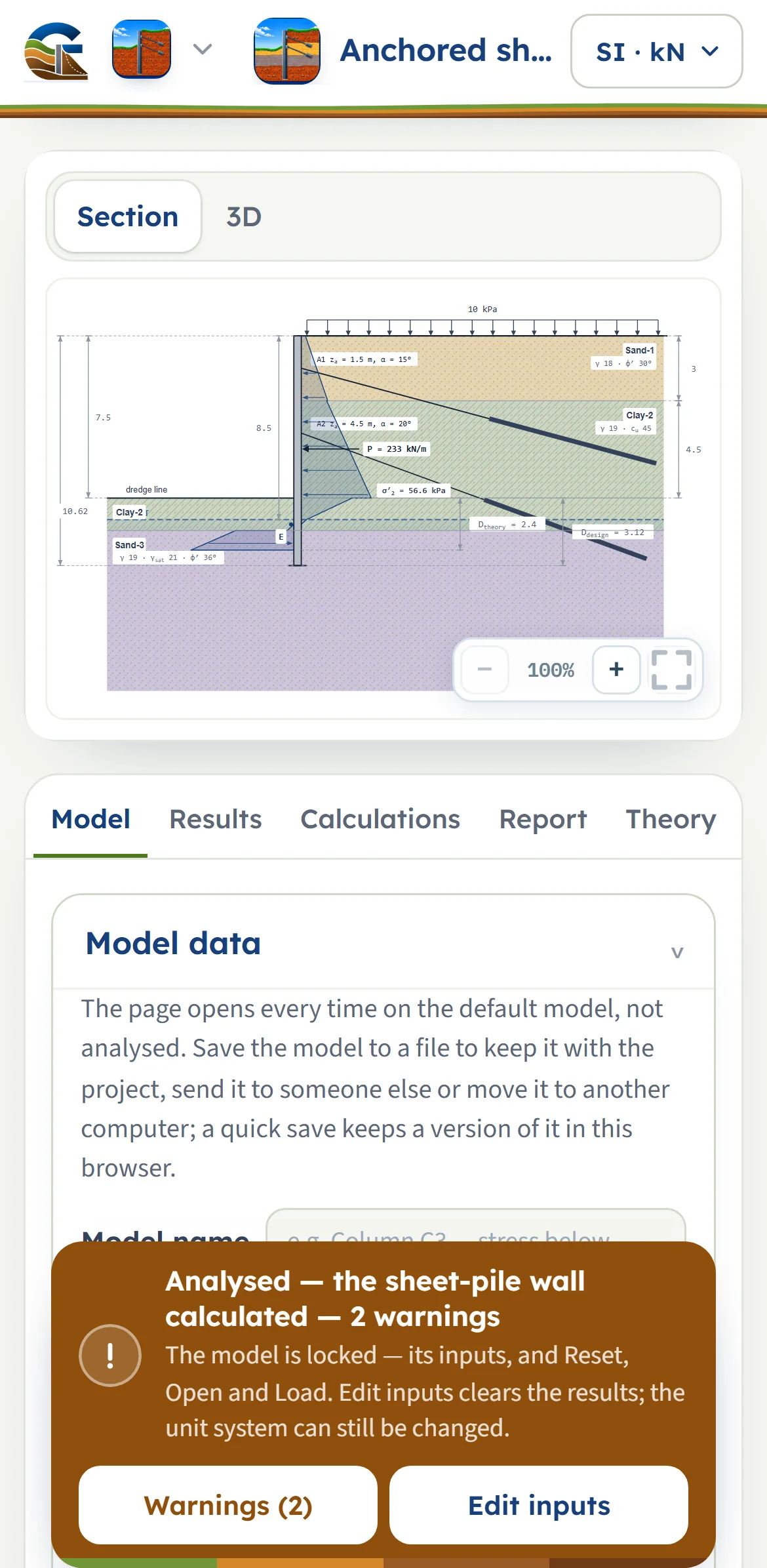
The model the Model tab opens with is a wall retaining L = 7.5 m of sand (3.0 m) over clay (6.0 m) over sand, with the water table 8.5 m below the top on both faces, a uniform surcharge q = 10 kPa and two rows of anchors — at 1.5 m and 4.5 m, spaced 2.5 m, inclined 15° and 20°. The margin is the factor f = 1.3 on the depth. Every number below is computed by the module's own code as this page opens; the same model is a bench record of the module, checked by an independent hand calculation.
| Layer | Soil | Thickness (m) | γ / γsat (kN/m³) | φ′ (°) | c′ (kPa) | cu (kPa) | Ka | Kp |
|---|---|---|---|---|---|---|---|---|
| 1 | sand | 3.0 | 18.0 / 20.0 | 30 | 0 | — | 0.3333 | 3.0000 |
| 2 | clay | 6.0 | 19.0 / 19.5 | 24 | 5 | 45 | 0.4217 | 2.3712 |
| 3 | sand | to the toe | 19.0 / 21.0 | 36 | 0 | — | 0.2596 | 3.8518 |
The long term, by hand, above the dredge line
Above the water table and the dredge line only σ′v and the drained pressure equation are needed:
In the short term the same clay is undrained: at its top σv − 2cu = 64.0 − 90 = −26.0 kPa < 0, so the soil pressure is cut to zero and a water-filled crack opens down to zc = 4.37 m, where σv = 2cu, as in the tension-crack equation.
The two scenarios
| Short term | Long term | Design (the larger) | |
|---|---|---|---|
| Dtheory (m) | 1.549 | 2.403 | 2.403 |
| Dreq = f · Dtheory (m) | 2.014 | 3.124 | 3.124 |
| F1 (kN/m) | 34.30 | 41.69 | 41.69 |
| F2 (kN/m) | 56.94 | 132.32 | 132.32 |
| Mmax (kN·m/m) | 59.49 | 121.43 | 121.43 |
| zM (m) | 6.546 | 6.825 | 6.825 |
The anchors
The sheet pile, the heave and the displacement
By subgrade reaction the top of the wall moves 2.6 mm back toward the retained side — pulled by the prestressed anchors, and the wall at the dredge line 11.2 mm toward the excavation: characteristic and indicative.
20What the module assumes, and what it does not dothe assumptions, the messages and the limits in one place
Every calculation rests on assumptions. The module sorts them by how they reach the report:
- Declared — no wall friction (δ = 0); the margin of the free length measured along the tendon; the point load taken at its most loaded section; the seismic coefficients layer by layer.
- Declared and shown both ways — the short- and the long-term scenarios (both run); the crack water-filled or dry (the other printed); the margin on the depth or on the passive pressure (the other printed).
- Stops — an anchor outside the wall; a layer without the strength its scenario needs; no admissible embedment; anchors in compression in every scenario; a failed closure; a bond zone inside the critical wedge.
| Condition | Level | What happens |
|---|---|---|
| Anchor outside 0 < za < L; two rows closer than 0.25 m | stop | nothing is calculated |
| A layer without cu (short term) or φ′ (drained) | stop | the layer and the scenario are named |
| No admissible embedment; the anchors in compression in every scenario; closure failed | stop | the pressure diagram is drawn |
| Free length shorter than sc + max(1.5 m, L/5) | stop | the bond zone would lie inside the wedge |
| Unequal water levels | validity banner | PRELIMINARY, no PASS verdict; the piping check named |
| Dry crack; no critical surface; short embedment; weak bond; tendon over capacity; toe block above E; row in compression; seismic domain; deep-seated stability | caution | reported with what was assumed |
| Cut-off active; several roots; the scenarios; point load moved to 0.30 m | note / info | the fact and the assumption |
The screen may suggest what to do next; the report only states what was assumed and found.
What the module does not do yet
- Rowe's moment reduction for a flexible wall — read from families of charts; to come with its own validation.
- Deep-seated stability and the overall stability of the wall and the ground — named as not checked in every anchored run.
- Seepage — unequal water levels are hydrostatic and carry the validity banner.
- A sloping retained surface, line loads and construction stages — later releases.
21Referencesthe source, the anchors, the codes
- Das, B.M. (2016). Principles of Foundation Engineering, 8th ed. Cengage Learning.
- Rankine, W.J.M. (1857). On the stability of loose earth. Philosophical Transactions of the Royal Society of London, 147, 9–27.
- Mononobe, N. and Matsuo, H. (1929). On the determination of earth pressure during earthquakes. World Engineering Congress, Tokyo. Okabe, S. (1926). General theory of earth pressure. Journal of the Japan Society of Civil Engineering, 12(1).
- Westergaard, H.M. (1933). Water pressures on dams during earthquakes. Transactions of the American Society of Civil Engineers, 98, 418–433.
- Bowles, J.E. (1996). Foundation Analysis and Design, 5th ed. McGraw-Hill.
- Brent, R.P. (1973). Algorithms for Minimization without Derivatives. Prentice-Hall.
- EN 1993-1-1:2005 — Design of steel structures, general rules.
- ANSI/AISC 360-22 — Specification for Structural Steel Buildings.
From theory to your own design
Design your own anchored wall in minutes
- Sand and clay layers, water on both faces, surcharges and the earthquake, with short-term and long-term scenarios
- Up to four rows of inclined anchors: forces, free length, bond and lock-off load
- Embedment, shear and moment, the sheet pile checked to EN 1993-1-1 or AISC 360-22, bottom heave and displacement
- A clean calculation report, saved as a PDF. Works on your phone and in your browser