

On this page · 14 chapters
A wall of granular fill with strips, sheets or grids inside it holds itself up: the fill takes the compression, the reinforcement the tension, the friction between them holds the two together. This page explains, section by section, how the module checks such a wall: the stresses in the fill and the surcharges, the failure surface that divides every level into a held and a holding part, the tension of a level, its rupture and its pullout, the reinforced block as a gravity wall against overturning, sliding and bearing, the earthquake, a worked example whose every number is computed by the module’s own code, and the assumptions.
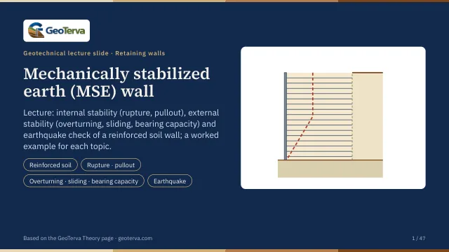 PDF
Lecture slides
Ready-made slides for lectures and self-study
The mechanism, the derivation, the equations and the figures of this page, in teaching order. Every slide links back to its chapter.
1A reinforced-soil wallwhat it is, what has to be checked, and the two procedures of the module
A wall of earth can stand on its own only at the angle of repose of its soil. Put thin tensile elements into the fill as it is placed — strips of galvanized steel, sheets of a woven fabric, a polymer grid — and the fill and its reinforcement act together: the soil carries the compression, the reinforcement the tension the soil cannot take, and the friction between the two holds them together. The front of the fill is closed by a facing of concrete panels, modular blocks or a wrap of the reinforcement itself, which keeps the soil in and carries little else. The idea is old; its systematic design began with Vidal in 1966 and the first walls with metal strips, and the fabrics and grids followed in the seventies and eighties. The source calls such walls mechanically stabilized; the practice says MSE walls.
The fill is a free-draining granular soil: a clayey fill would develop pore pressures and lose strength, and the practice does not use it. The design has two parts (the source; FHWA):
- Internal stability. Every level of reinforcement must carry the tension the fill puts on it without breaking (rupture), without being pulled out of the fill behind the failure surface (pullout), and without tearing off the facing (the connection). These checks set the strength, the spacing and the length of the reinforcement (Sections 2 to 6).
- External stability. The reinforced block, L wide and H high, is a gravity wall: the retained fill pushes on its back, and it must not overturn, slide on its base or fail the soil under it (Sections 7 to 9).
- The earthquake. Both sets of checks again, with the dynamic thrust of the retained fill, the inertia of the block and the inertia of the fill the reinforcement holds (Section 10).
- Global stability — a slip surface through the foundation soil below the wall, or a compound one through the block — is checked by a slope stability analysis and is not part of this module.
Two procedures are offered. The source takes the Rankine active pressure at every depth and the Rankine wedge from the toe as the failure surface, for every kind of reinforcement. The simplified method of FHWA and AASHTO, which is the practice of the design codes, raises the lateral stress for stiff (inextensible) reinforcement and moves its failure surface closer to the facing, and lays down how the live load, the pullout resistance and the eccentricity of the resultant are to be taken. The module carries both; the simplified method, the one for a wall to be built, is the choice it opens with.
2The stresses in the fillthe Rankine pressure, the stress ratio of the practice, and the surcharges
The fill behind the facing is in the active state: it has moved just enough for its strength to be mobilised, and the lateral stress on a vertical plane is the Rankine active pressure. With z the depth below the top of the wall, γ1 the unit weight and φ′1 the friction angle of the reinforced fill,
The lateral stress ratio of the simplified method
Field measurements and the tests behind the practice show that stiff reinforcement — steel strips, bar mats — holds the fill back harder than the Rankine state near the top of the wall, where the fill has not strained enough to reach it, and that the stress ratio falls with depth; extensible geosynthetics strain enough for the Rankine pressure to be right. The simplified method (AASHTO LRFD 11.10.6.2.1, FHWA) takes Kr/Ka by the kind of reinforcement, with Ka of the reinforced fill:
Surcharges
A uniform surcharge adds to the vertical stress at every depth and, through Kr, to the lateral stress. The Model tab takes one uniform surcharge q, as a live load, qL = q; the calculation also knows a permanent one, qD, and the strip loads below, which the form offers in a later release. Both kinds load the reinforcement and push on the block, but a live load is not counted where it would help — in the weight that resists sliding and overturning and in the vertical stress that holds the reinforcement against pullout (the practice; the source has one surcharge). Taking the surcharge as live is the safe side in every check.
A strip load of intensity qs and width a′ at a distance b′ from the facing — the footing of a bridge seat or a building — is taken as the source does, after Laba and Kennedy (1986): the vertical stress spreads two vertical to one horizontal, and the lateral pressure follows the elastic solution for a strip load on a rigid wall, raised by a factor M that is 1.4 for a strip at the facing and 1 for a strip more than 0.14 H back. Several strips act together — the elastic solutions are linear, so the vertical stress and the lateral pressure of each add — and a strip, like a uniform load, is permanent or live. The calculation of the module carries them; the form of the Model tab offers the uniform surcharge for now, as the braced cuts do, with the strip load marked Soon.
For the worked wall, at the base: σ′v = 16.5 × 10 = 165 kPa; Ka = 0.2596, Kr = 1.2 Ka = 0.3115 and σ′h = 51.4 kPa. At the top level, 0.6 m down, Kr/Ka is 1.65.
3The failure surface and the lengthsthe active and the effective length of a level
The reinforcement works where the fill would otherwise fail. The part of a level inside the failure zone — between the facing and the failure surface — is pulled along with the sliding soil and does not hold it; only the part beyond the surface, in the stable fill, anchors the level. The failure surface therefore divides every level into an active length La and an effective length Le = L − La.
The source takes the Rankine wedge from the toe for every reinforcement, a plane at 45° + φ′1/2 to the horizontal: at the top of a 10 m wall in a fill of 36° it is 5.1 m behind the facing. Measurements in walls with steel strips show the surface of greatest tension much nearer the facing — stiff reinforcement does not let the fill strain enough for the Rankine wedge to form — and the practice takes for inextensible reinforcement a bilinear surface, vertical at 0.3 H behind the facing over the upper half of the wall and straight down to the toe from there. For extensible reinforcement the practice keeps the Rankine surface. In the simplified method of the module a metallic strip takes the bilinear surface and a geosynthetic the Rankine one; the source’s procedure takes the Rankine surface for both.
4The tension of a levelthe levels and what each holds
Each level holds the lateral stress of the fill between the mid-heights to its neighbours — its tributary height, SV for even levels. The source places the levels at SV, 2 SV, …, N SV = H, the last at the base where the stress is largest, and the module does the same; when H is not a multiple of SV the last level is put at the base, closer than SV to the one above it, and still taken to carry SV of fill. A strip holds the fill over its horizontal spacing SH as well; a sheet or a grid is continuous and the tension is per metre of wall.
When the fill and a uniform surcharge are all that load the wall, the largest tension is at the base, Tmax = σ′h(H) SV SH; a strip load near the facing can move it to an upper level, and the module takes the largest over the levels. It sets the thickness of the strips or the spacing of the sheets, which the convention keeps the same at every level. Where the simplified method raises Kr near the top, the top levels carry more than the Rankine value, but the base still governs unless a load near the facing adds to the top.
5Rupturecorroded strips, reduced geosynthetics, and the required thickness or spacing
A level breaks when its tension reaches what the reinforcement can carry.
Galvanized steel strips
A strip of width w and thickness t carries w t fy, fy the yield strength of the steel. Galvanized steel corrodes in the fill, 0.025 to 0.050 mm a year by the source; over the design life n the strip loses r n of its thickness, which is taken off before the strip is checked (the source). The required factor against rupture, FSB, is 2.5 to 3 in the source; the practice allows 0.55 fy on the corroded section, a factor of 1.8.
Turned round, the thickness the design needs is that of the largest tension with the corrosion allowance put back (the source):
Geotextiles and geogrids
A geosynthetic is given by its ultimate wide-width tensile strength Tult, per metre of width. Its long-term strength is less: it is damaged when the fill is placed and compacted on it, it creeps under a sustained load, and it degrades chemically and biologically. The source divides Tult by a factor for each:
| Factor | Geotextile | Geogrid |
|---|---|---|
| Installation damage RFid | 1.1 – 2.0 | 1.1 – 1.4 |
| Creep RFcr | 2 – 4 | 2 – 3 |
| Chemical and biological degradation RFcbd | 1 – 1.5 | 1.1 – 1.5 |
A geogrid does not always cover the whole plan: rolls 1.2 m wide laid with 0.3 m between them cover Cr = 1.2/1.5 = 0.8 of it, and a metre of wall carries Tall Cr. The spacing the required factor allows at the base is SV = Tall Cr/(σ′h(H) FSB).
For the worked wall the strip, 75 × 6 mm placed, is 75 × 4.75 mm after 1.25 mm of corrosion over 50 years, and carries 85.5 kN; the largest tension is 30.8 kN, so FS(B) = 2.77 against 1.80 required, and the thickness the required factor asks for is 4.33 mm.
6Pulloutthe friction beyond the failure surface, F* and α, the required length
A level that does not break can still slide out of the fill. Beyond the failure surface the fill holds it by friction on its two faces, and the friction is the vertical stress on the level times the factor the reinforcement mobilises:
- F* is the pullout resistance factor, the friction the reinforcement can mobilise per unit of the vertical stress. The source writes it as tan φ′μ, the soil–tie friction angle, for a strip; as tan φ′F ≈ tan(⅔ φ′1) for a geotextile, with measured ratios φ′F/φ′1 of 0.8 to 1.0 for sand (as the source quotes them); and as Ci tan φ′1 for a geogrid, Ci the interaction coefficient, 0.75 to 0.8 for a gravel, 0.7 to 0.75 for a well-graded sand, 0.55 to 0.6 for a fine or silty sand. The practice gives F* from pullout tests, and without them takes ⅔ tan φ′ for a geosynthetic; for ribbed steel strips it takes F* from 1.2 + log Cu at the top of the wall down to tan φ′ at 6 m. The module fills F* in as a lower bound — tan φ′1 for a strip, ⅔ tan φ′1 for a geosynthetic — and lets it be typed over.
- α is the scale effect correction of the practice, for the fact that a long extensible reinforcement does not mobilise its friction along its whole length at once: 1.0 for metallic strips, 0.8 for a geogrid, 0.6 for a geotextile. The source has none (α = 1).
- σ′v is the vertical stress on the level in the resisting zone, γ1 z with the permanent surcharges and strip loads, without the live loads.
For a strip with no surcharge both T and Pr grow with the depth: by the source’s procedure the effective length the required factor asks for is then the same at every level, and the required length follows the failure surface, longest at the top; in the simplified method the top levels carry Kr/Ka times more and need an effective length longer in the same proportion. A surcharge that loads the level without holding it — the live load — lowers the factor; a dead surcharge does not change it.
The lap of a geotextile, and the connection
A geotextile wall is faced by wrapping each sheet round the fill of its level and lapping it back under the next sheet; the lap holds the same tension on both its faces, so its length is half the effective length the level needs, and never less than 1 m (the source, with F* α for the friction as in the pullout):
Where the reinforcement is fixed to a facing of panels or blocks, the connection must carry the tension of the level; the practice takes the load at the connection as Tmax and the strength from connection tests. If that strength is entered, the module checks it with the rupture factor.
For the worked wall the least pullout factor is at level 1, 0.6 m down: La = 3.00 m, Le = 4.50 m, Pr = 2 × 0.075 × 0.727 × 9.9 × 4.50 = 4.86 kN against T = 2.54 kN: FS(P) = 1.91. The longest length asked for is 6.54 m, at level 1.
7The reinforced block: overturningthe thrust, the weights, and the eccentricity of the resultant
Internally sound, the reinforced block is still a block of soil holding back the fill behind it, and it is checked as a gravity wall L wide and H high (the source). The retained fill — the same granular soil in the source, its own soil in the module — pushes on the back of the block with its Rankine active thrust, plus the surcharges:
The block resists by its weight γ1 H L at L/2 from the toe, by the permanent surcharge on it and by the part of a permanent strip load that lies over it; a live load, uniform or strip, which may be absent when the thrust is there, is not counted as resisting (the practice).
Overturning, and the eccentricity of the resultant
The overturning factor is the ratio of the resisting moment of the weights about the toe to the overturning moment of the thrust. The practice puts the same check as a limit on where the resultant of all the forces meets the base: the eccentricity e of that point from the centre of the base must stay within L/6, so that the whole base stays in compression. The module gives both.
For the worked wall Pa = ½ × 0.2596 × 16.5 × 10² = 214.2 kN/m at 3.33 m, Mo = 714 kN·m/m; W = 16.5 × 10 × 7.5 = 1238 kN/m at 3.75 m, MR = 4641 kN·m/m: FS(overturning) = 6.50 and e = 0.58 m against L/6 = 1.25 m.
8Slidingthe friction on the base, on the weaker soil
The block slides on its base when the thrust exceeds the friction there. The source takes the friction as ΣV tan(k φ′1) with k ≈ ⅔, as for a concrete wall on soil; the base of a reinforced block is soil on soil, and the practice takes the friction angle of the weaker of the reinforced fill and the foundation soil (or the interface with a geosynthetic at the base). The module keeps the source’s ⅔ and takes the weaker soil, and counts no cohesion of the foundation; it prints, beside its own, the value with the fill alone, which is the source’s way.
For the worked wall the foundation soil, φ′2 = 28°, is the weaker: FS(sliding) = 1238 × tan(⅔ × 28°) / 214.2 = 1.95; with the fill’s 36°, as the source writes it, 2.57.
9Bearingthe source’s check and Meyerhof’s effective width
The foundation soil carries the block as it would a strip footing. The source takes the bearing capacity of a footing L wide on the surface, qu = c′2 Nc + ½ γ2 L Nγ — no depth term, since the base is at the surface or the embedment is not counted — and compares it with the vertical stress under the block at the base, σ′o(H) = γ1 H plus the surcharge. The factors Nc and Nγ are those of the general bearing capacity equation.
The resultant on the base is not at its centre: the thrust pushes it towards the toe by the eccentricity e, and the pressure under the toe is more than the average. The practice (FHWA, AASHTO) puts the resultant on Meyerhof’s effective width L − 2e, carrying the whole vertical load, live load included, as a uniform pressure, and computes the capacity of a footing of that width. The pressure is higher and the footing narrower, so the factor is lower; the module computes both and the lesser governs.
| φ′2 | Nc | Nγ |
|---|---|---|
| 20° | 14.83 | 5.39 |
| 25° | 20.72 | 10.88 |
| 28° | 25.80 | 16.72 |
| 30° | 30.14 | 22.40 |
| 35° | 46.12 | 48.03 |
| 40° | 75.31 | 109.41 |
For the worked wall: the source’s way, qu = 50 × 25.80 + ½ × 17.3 × 7.5 × 16.72 = 2375 kPa over σ′o(H) = 165 kPa, FS = 14.39; with the eccentricity, L′ = 7.5 − 2 × 0.58 = 6.35 m, σ′v = 195 kPa, qu = 2208 kPa and FS = 11.32, which governs.
10The earthquakeMononobe–Okabe, the inertia of the block and of the levels
An earthquake adds to the static case. The practice (FHWA, AASHTO) treats it with a horizontal seismic coefficient kh and three forces:
- The dynamic thrust of the retained fill by Mononobe–Okabe: the active coefficient KAE for a vertical wall, a level surface and no wall friction, with ψ = tan−1 kh; the increment over the static thrust is ΔPAE = ½ γb H² (KAE − Ka), of which half is applied — the thrust and the inertia of the block do not peak together — at 0.6 H above the base.
- The inertia of the reinforced block over a width of 0.5 H behind the facing, PIR = ½ kh γ1 H², at mid-height.
- The inertia of the active zone, Pi = kh Wa, Wa the weight of the fill between the facing and the failure surface, shared among the levels in proportion to their effective lengths, so that each level carries Tmd = Pi Le/ΣLe on top of its static tension.
With these the block is checked again for overturning, with the resultant allowed out to L/3, for sliding and for bearing, and every level for rupture with T + Tmd and for pullout with the friction at 80 % of its static value; the factors required are 75 % of the static ones. The live load is kept as in the static case — it loads and does not resist; the practice allows it to be reduced or left out of the seismic combination, and the module keeps it, on the safe side. The surcharges add no inertia.
For the worked wall with kh = 0.15: KAE = 0.3468 against Ka = 0.2596, ΔPAE = 71.9 kN/m, PIR = 123.8 kN/m; the factors fall from 6.50 / 1.95 / 11.32 (overturning, sliding, bearing) to 3.00 / 1.12 / 8.13, and the least factors of the levels from 2.77 and 1.91 to 2.41 and 0.74.
11Reading the resultswhat each result is, and the drawings
The Results tab gives every check as a factor against its required value: rupture and pullout (the least over the levels), overturning, the eccentricity against L/6, sliding and bearing, the connection when its strength is given, and the same under the earthquake when kh is given; then the largest tension, the thickness (strips) or the spacing (geosynthetics) the required factor asks for, the length the pullout check asks for, the lap of a geotextile, and the thrust.
- Section draws the wall: the facing, the levels, the failure surface of the chosen procedure, the surcharges, the retained fill and the foundation soil; after Analyze each level is coloured by its factors and a tick marks the length it needs.
- Stresses draws σ′v and σ′h with depth, part by part, and the tension of every level against what it carries.
- Levels draws the two factors of every level against the required ones, with the earthquake beside them, and the length each has against the one it needs.
- Block draws the forces on the block, the resultant on the base and the pressure on the effective width, and the three factors; with an earthquake, the seismic forces and factors.
The Calculations tab writes the working level by level in a table, with the governing levels worked out in full, and the external checks force by force. The required factors are inputs: the help of each quotes the source and the practice.
12A worked exampleevery number computed by the module’s own code
The model the Model tab opens with: a wall 10 m high of granular fill (γ1 = 16.5 kN/m³, φ′1 = 36°) reinforced by galvanized steel strips 75 × 6 mm of fy = 240 MPa, 7.5 m long at SV = 0.6 m and SH = 1.0 m, corroding 0.025 mm a year over 50 years; the retained fill the same soil; a foundation of φ′2 = 28° and c′2 = 50 kPa; no surcharge; the simplified method. Every number below is computed by the module’s own code as this page opens.
- Stresses (Section 2): at the base σ′v = 165 kPa, Kr = 1.2 Ka = 0.3115, σ′h = 51.4 kPa, Tmax = 30.8 kN per strip.
- Rupture (Section 5): Tcap = 85.5 kN, FS(B) = 2.77 (1.80 required); treq = 4.33 mm.
- Pullout (Section 6): the least factor 1.91 at level 1 (1.50 required); the longest length asked for 6.54 m against 7.5 m.
- The block (Sections 7 to 9): Pa = 214 kN/m, W = 1238 kN/m; overturning 6.50, e = 0.58 m (L/6 = 1.25 m), sliding 1.95, bearing 11.32 (by the source’s way 2.57 and 14.39).
The same wall with other choices
| Case | FS(B) | FS(P) | Lreq (m) | FSot | e (m) | FSsl | FSbc |
|---|---|---|---|---|---|---|---|
| As entered (strips, the simplified method) | 2.77 | 1.91 | 6.5 | 6.50 | 0.58 | 1.95 | 11.32 |
| The same wall by the source’s procedure (Rankine, the wedge from the toe) | 3.33 | 1.90 | 6.9 | 6.50 | 0.58 | 1.95 | 11.32 |
| The source’s procedure with L = 13.5 m | 3.33 | 6.10 | 6.9 | 21.06 | 0.32 | 3.51 | 18.18 |
| With a live surcharge of 20 kPa | 2.47 | 0.63 | 13.7 | 4.77 | 0.79 | 1.57 | 9.54 |
| With a strip load of 60 kPa, 2 m wide, 1 m from the facing (in the calculation; the form offers it later) | 2.74 | 1.32 | 8.1 | 3.66 | 1.14 | 1.55 | 7.87 |
| With an earthquake, kh = 0.15 | 2.77 | 1.91 | 6.5 | 6.50 | 0.58 | 1.95 | 11.32 |
| A geogrid of Tult = 150 kN/m at 0.6 m | 1.25 | 10.78 | 5.2 | 6.50 | 0.58 | 1.95 | 11.32 |
| L = 0.7 H = 7 m | 2.77 | 1.70 | 6.5 | 5.66 | 0.62 | 1.82 | 10.60 |
By the source’s procedure the same strips need 6.9 m at the top (the Rankine wedge reaches 4.79 m back) and the least pullout factor with 7.5 m is 1.90; with L = 13.5 m it is 6.10, and the rupture factor is higher, 3.33, because Ka replaces 1.2 Ka at the base. A live surcharge of 20 kPa lowers every factor — FS(P) to 0.63, sliding to 1.57 — since it loads and does not hold; the strip load of 60 kPa lowers them less (1.32 and 1.55) because its weight over the block resists and its lateral pressure is spread. A geogrid of 150 kN/m at the same spacing has FS(B) = 1.25 and, with the Rankine surface and α = 0.8, FS(P) = 10.78. At 0.7 H = 7 m the strips keep FS(P) = 1.70 and the block FS(sliding) = 1.82 with e = 0.62 m.
13What the module assumes, and what it does not dothe assumptions and the limits in one place
Every analysis rests on assumptions. The module sorts them by how they reach the results:
- The fill. Free-draining granular soils, reinforced and retained, without pore pressure; no water table in or behind the wall, no sloping backfill above it (a slope or a broken-back fill is a later addition).
- The levels. One length at every level, placed at SV, 2 SV, … down to the base, each carrying SV of fill; the convention of the source, which the practice shares for even spacings. Levels of different lengths, or a trapezoidal section, are not modelled.
- The lateral stress. Rankine Ka, or the simplified method’s Kr/Ka for strips and geosynthetics; bar mats and welded wire, whose ratio starts at 2.5, are not in the module. The strip loads follow Laba and Kennedy and add up; a point load or a line load is not modelled. The Model tab offers the uniform surcharge, taken as live; the strip load is in the calculation and comes to the form in a later release.
- The pullout. F* α σ′v on two faces beyond the failure surface, with the F* the engineer gives or the module’s lower bound; the depth-varying F* of ribbed strips and the passive resistance of transverse bars are not modelled, which is on the safe side.
- The facing carries nothing and resists nothing; its own stability is outside the module, and the connection of the reinforcement to it is checked only when its strength is entered — without it the Results and the report give the load the connection would carry (Tmax, and Tmax plus the inertia of the active zone under the earthquake). The embedment in front of the wall is not credited.
- The block. A rigid gravity wall with the Rankine thrust of the retained fill on a vertical back; sliding on ⅔ of the lesser friction angle without cohesion; bearing by the general equation on the surface, the source’s way and on the effective width.
- The earthquake. Mononobe–Okabe with no wall friction and kv = 0, half the dynamic increment at 0.6 H, the inertia of the block over 0.5 H, the inertia of the active zone shared by the effective lengths; kh is the engineer’s.
- Not checked. The global and the compound stability (a slope stability analysis), the settlement of the wall and the differential settlement along it, the drainage, the facing, the construction stages.
The checks are those of the source and of the design practice of FHWA and AASHTO in their working-stress form — global factors of safety on the resistances (1.8 rupture, 1.5 pullout, 2 overturning, 1.5 sliding, 2.5 bearing, and 75 % of them under the earthquake), not the load and resistance factors of AASHTO LRFD and FHWA GEC 11 — with the required factors as inputs. They give a complete first design of a reinforced-soil wall; a wall that matters is finished with the product data of the reinforcement and the facing, a global stability analysis and the settlement of the foundation.
14Referencesthe source, the practice and the papers behind the factors
- Das, B.M. (2016). Principles of Foundation Engineering, 8th ed. Cengage Learning, Boston. Chapter 13, Sections 13.10 to 13.17: soil reinforcement, the design of walls with metallic strips, geotextiles and geogrids; Table 4.2 for the bearing capacity factors.
- Berg, R.R., Christopher, B.R. and Samtani, N.C. (2009). Design of Mechanically Stabilized Earth Walls and Reinforced Soil Slopes, Vol. I, FHWA-NHI-10-024. Federal Highway Administration, Washington, D.C.
- American Association of State Highway and Transportation Officials (2012). AASHTO LRFD Bridge Design Specifications, 6th ed., Section 11.10, Mechanically stabilized earth walls.
- Vidal, H. (1966). La terre armée. Annales de l’Institut Technique du Bâtiment et des Travaux Publics, Paris, July–August, 888–938.
- Laba, J.T. and Kennedy, J.B. (1986). Reinforced earth retaining wall analysis and design. Canadian Geotechnical Journal, 23(3), 317–326.
- Koerner, R.M. (2005). Designing with Geosynthetics, 5th ed. Prentice Hall, Englewood Cliffs, N.J.
- Binquet, J. and Lee, K.L. (1975). Bearing capacity analysis of reinforced earth slabs. Journal of the Geotechnical Engineering Division, ASCE, 101(GT12), 1257–1276.
- Martin, J.P., Koerner, R.M. and Whitty, J.E. (1984). Experimental friction evaluation of slippage between geomembranes, geotextiles and soils. Proceedings, International Conference on Geomembranes, Denver, 191–196.
- Mononobe, N. and Matsuo, H. (1929). On the determination of earth pressures during earthquakes. Proceedings, World Engineering Congress, Tokyo, 9, 177–185.
- Okabe, S. (1926). General theory of earth pressure. Journal of the Japanese Society of Civil Engineers, 12(1).
- Vesic, A.S. (1973). Analysis of ultimate loads of shallow foundations. Journal of the Soil Mechanics and Foundations Division, ASCE, 99(SM1), 45–73.
From theory to your own design
Check your own reinforced-soil wall in minutes
- The tension, the rupture and the pullout of every level
- The thickness, spacing and length the required factors ask for
- Overturning, eccentricity, sliding and bearing of the block, and the same under the earthquake
- A clean calculation report, saved as a PDF. Online: nothing to install, no dongle, on a phone, a tablet or a PC